Warning and alternatives.
Before going any further... Understand that I'm a biologist, not an engineer. The transmitter described here was designed while learning how to build transmitters. There are probably much better ways to do things. For open-source ARDF receivers and transmitters being designed by people with much more experienced (Charles Scharlau and Jerry Boyd), check out openardf.org.
But, if you're like me, this shows what you can do with a few years of study and experimentation in the evenings and on weekends. The transmitter described here works and has been used for ARDF events in the Chapel Hill area in 2016 and 2017.Introduction.
This page describes an 80m ARDF transmitter. It was designed around the ATmega328 as the microcontroller and the Si5351 as the source RF signal. We wanted a totally open source (code and hardware) transmitter available to anyone interested in putting on ARDF events or just building one to practice. The following criteria were used.
- The user should be able to choose among a number of frequencies.
- The user should be able to choose the type of fox for the transmitter (HB, MOE, MOI, ...).
- The user should be able to choose the cycle length (ie the number of foxes).
- The power output should be adjustable and it should be possible to get more than 1 W output into a 50-ohm dummy load.
- It should be as simple as possible to build.
The transmitter described here has been used since the Spring of 2016 at Chapel Hill-Carrboro City Schools ARDF events. Plans are to also start using them in the Spring of 2017 for some Backwoods Orienteering Klub events.
The plan is to put all the information needed to build the transmitter on the web site. This will include the schematics, the layout, the BOM, the code to load onto the ATmega328. Also I'll put up notes about the building, testing, and use. It will probably take a very long time to put all up. The code isn't even completely written yet. And generally, the priority will always be running the ARDF events. But eventually I want to have all the information that someone would need to build the transmitter.
2017-05-01: Update - web page under construction.
Currently under construction: I started update on 2017-05-01 to get up to version 5. I should be done in a week or so.
For earlier updates, see bottom of page.
Changes to project since the last update:
- Tests with shorter antennas for foxes gave disappointing results. We're keeping the longer antennas.
- Test with 10 batteries also gave disappointing results. We're keeping 16 batteries and planning on adding a switching voltage regulator between the battery pack the and the PCB.
- An option has been added in the code to delay RF output for two hours from power-on time if pin PB2 on the ATmega is pulled to ground. This can be done with a jumper on the P302 header. It's not documented yet.
Changes to web page since last update:
- The OSH Park PCB has been changed from version 2 to the current version 5.
- Added "changes needed" section.
- Added warning at top about design being by hobbyist. And added a link to openardf.org.
- Updated image of schematic from version 2 to version 5.
- Added build note PDFs
Still to do:
- Add kicad project.
- Add code.
General overview of the transmitter.
The info presented here is for version 5. We haven't built any of the version 5 transmitters yet but I'm feeling confident that they're ok to put up because the changes from version 4 were minor.
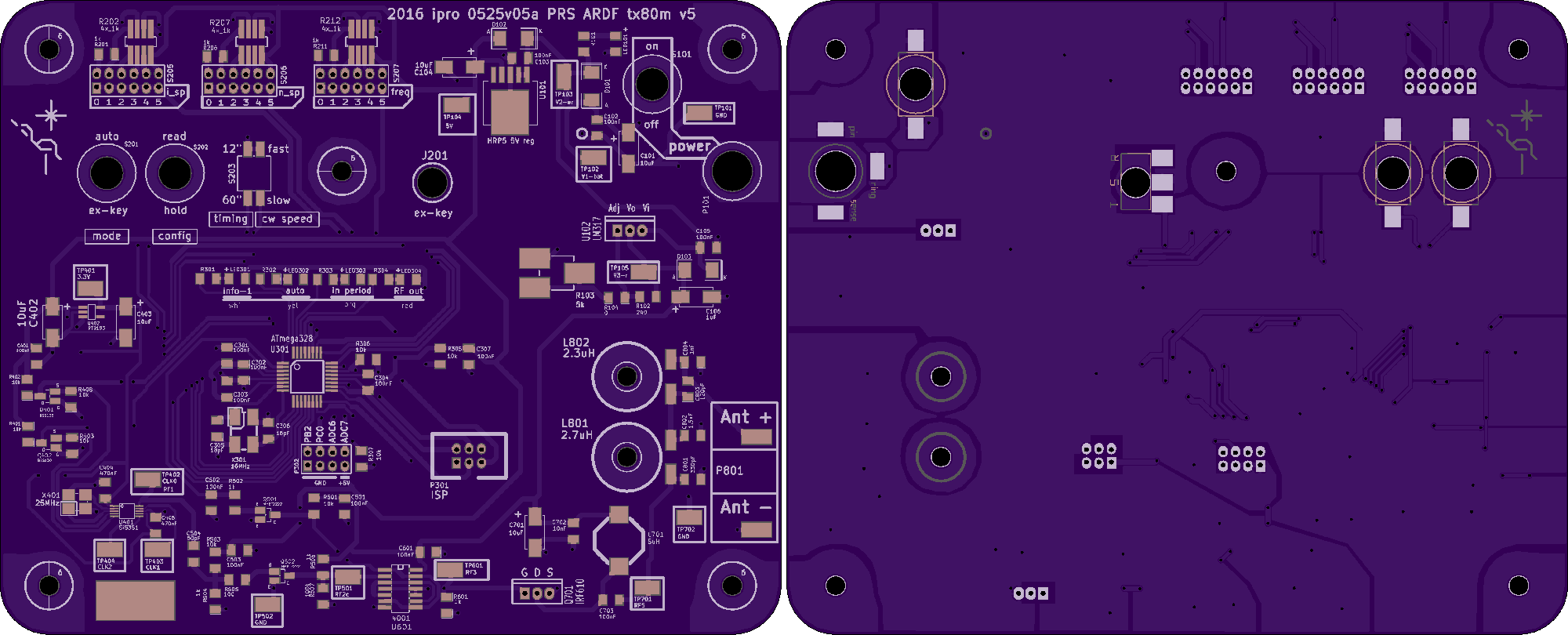
First a look at the nice OSH Park PCB (from version 5).

OSH Park PCB. The top is on the left the bottom (bottom-view) on the right. Link to full size image.
Here is a general overview. The 'flow' is generally from the upper right corner, leftward, then down to the lower left corner, and finally rightward. Most of the voltage regulation is in the upper right. The battery wires will enter at P101 via a barrel connector. U101 generates 5 V needed by most components and U102 generates the regulated high voltage for RF output. Then the user input in the upper left. There are configuration inputs are those labeled: i_sp, n_sp, freq, mode, config, timing, and cw speed. At the label 'ex-key' (J201) there is a jack for manually keying the transmitter. Below all this and toward the center sits the ATmega328 controlling everything. Also there are a row of informative LEDs labeled info-1, auto, in period, and RF out. In the bottom, the RF is generated by the Si5351 at the far left and ends at the antenna pads at the far right.
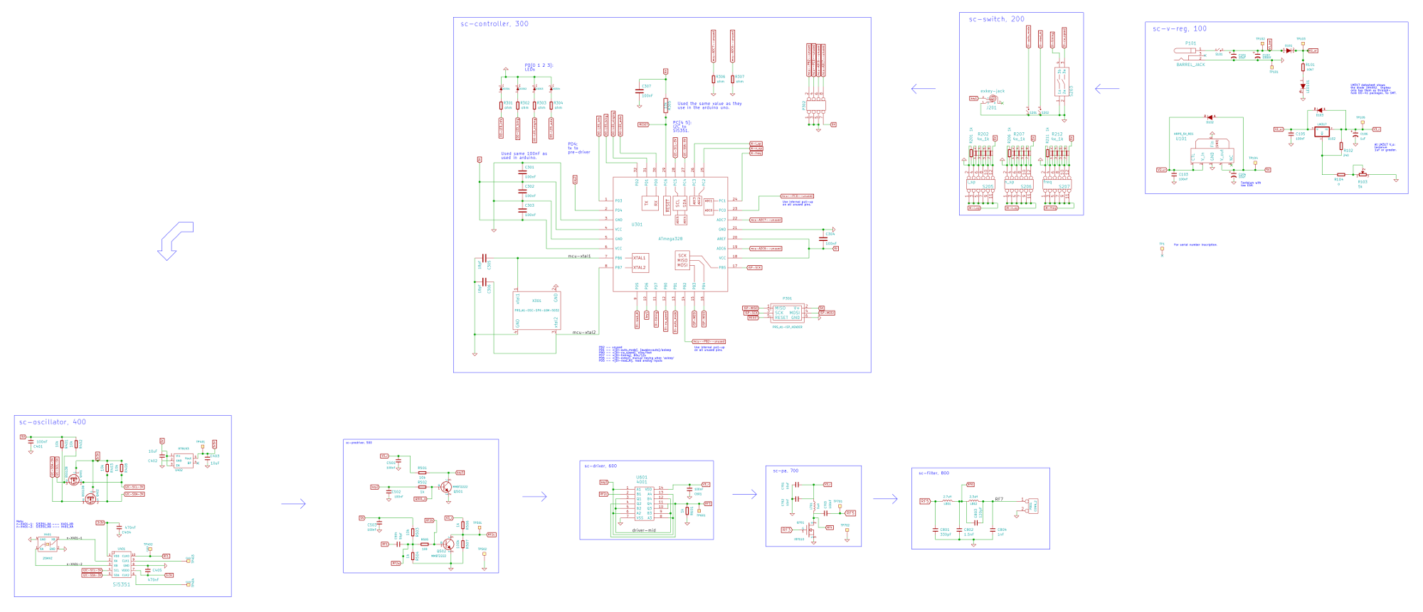
The schematic follows the same general pattern as the PCB. To see it all clearly, you should download the large file. In the future, I'll make a block diagram and break the schematic file into individual modules.

Schematic for version 5.
Full size (1 MB).
Looking at the schematic, you'll see how it is divided into a number of functinal modules: voltage regulator, switches (user input), controller (ATmega), oscillator (Si5351), pre-driver (MMBT222, was 2n2222 in older versions), driver (4001), power amplifier (IRF610), and filter.
Why the ATmega328 and why the Si5351.
The ATmega328 is the microcontroller used in the most popular Arduino, the Uno. There is such a huge community behind it! It's wonderful.
The Si5351 was chosen because a number of amateur radio DIY builders have experimented with it and put their results and code on the web. We were looking for a way to have several frequencies available but we wanted the stability provided by a crystal. The Si5351 itself uses an external crystal as a base from which to generate an output frequency. That output frequency is set using I2C. We're currently (2017 March) using simple crystals as the time base for the Si5351. But we'll probably experiment with a TCXO for improved stability in the current version (version 5).
Changes from version 4 to version 5.
The main change in going from v4 to v5 was going from 2N2222 to MMBT2222 for Q501 and Q502. But we had already tested this with one of the v4 transmitters on which we had soldered a mini breakout board with an MMBT2222 onto the 2N2222 pads. I think the list below contains all the changes, although I may have missed one.
- Used MMBT2222 instead of 2N2222.
- All test point pads were made slightly larger.
- Added two more testpoints for ground (TP502, TP702).
- Created new kicad modules for some diodes (D101, D102, D103). New ones have thicker silkscreen lines and extended pads.
- Created new kicad modules for SOT-23 and TO220. They Q501, Q502, U102, Q701.
- Created new kicad modules for 3x2 and 4x2 pin arrays.
My build notes.
I'm still making changes and these build notes are what I use as I build. So they are not guaranteed to be complete or entirely accurate. But they should help.
- Build notes (PDF): These are the notes I use during building.
- Testing notes (PDF): These are the notes I use during some of the testing I do.
Changes needed.
- The biggest problem is the power consumption. The linear regulator is wasting much energy. The current plan is to add a switching regulator between the battery pack and the PCB.
- It would be so nice to have an RTC to control the cycle timing. I'm not sure how to do that with the current boards but I'm hoping we can use the extra pins on header P302 to add a small RTC module.
- A barrel connector directly in the side would be nice for recharging. This is will probably happen before any other changes. It's pretty simple.
- A vent would be needed for the transmitter to dry out without having to open the top. This will come in handy when we add a barrel connector for charging so we don't need to open the top for charging anymore.
- A second (BNC) connector for antenna hookup would be nice. This may also happen soon since we're starting to use transformers or tuners between the transmitter and the antenna.
Update archive.
2017-03-07: Update.
We have version 5 OSH Park PCBs but building has slowed down for a bit. We were trying to get the 2 m transmitter going and trying to develop a course timing system. We're about to start the spring 2017 CHCCS ARDF season so things won't speed up for a while.
But we have a number of new plans.
- Reduce the number of batteries from 16 to 10.
- Alter the antenna setup to make it easier to set up.
- Experiment with a TCXO as the time base for the Si5351.
- We're thinking of replacing the linear regulators with switching ones.
Going to 10 batteries will limit the RF power we can put out. But we've kept it at 1 W for a long time and can hear that signal several km away with a 6 m vertical and four 3 m radials. Since we're using linear voltage regulators, the extra batteries are just extra weight. And hence the interest in switching regulators.
The antenna setup is definitely the longest time spent in transmitter deployment before an event. The complexity, also makes it difficult to ask others for help. So we have experiments planned to see if we can make that easier for the foxes. We'll probably keep the homing beacon the same as before.
Older stuff
The old page from 2016 may still be up. It can be found here.