The information below is out of date.
For current work on the 80m transmitter project,
go to the
2017 80 m transmitter page
.
Here I'm starting to document our 80 m ARDF transmitter.
The plan is to put all the information needed to build the transmitter. This will include the schematics, the layout, the BOM, the code to load onto the ATmega328. Also I'll put up notes about the building, testing, and use. It will probably take a very long time to put all up. The code isn't even completely written yet. And generally, the priority will always be using the equipment and experimenting. But eventually I want to have all the information that someone would need to build the transmitter.
Unlike blog entries, this page will change. As the transmitter gets new versions, this page will change to reflect this. But I started the page now (2016-03-02) precisely because I don't foresee major changes. The transmitter could definitely be greatly improved, especially by someone with an electronics background, but I'm moving on to other projects.
General overview of the transmitter.
First a look at the nice OSH Park PCB.
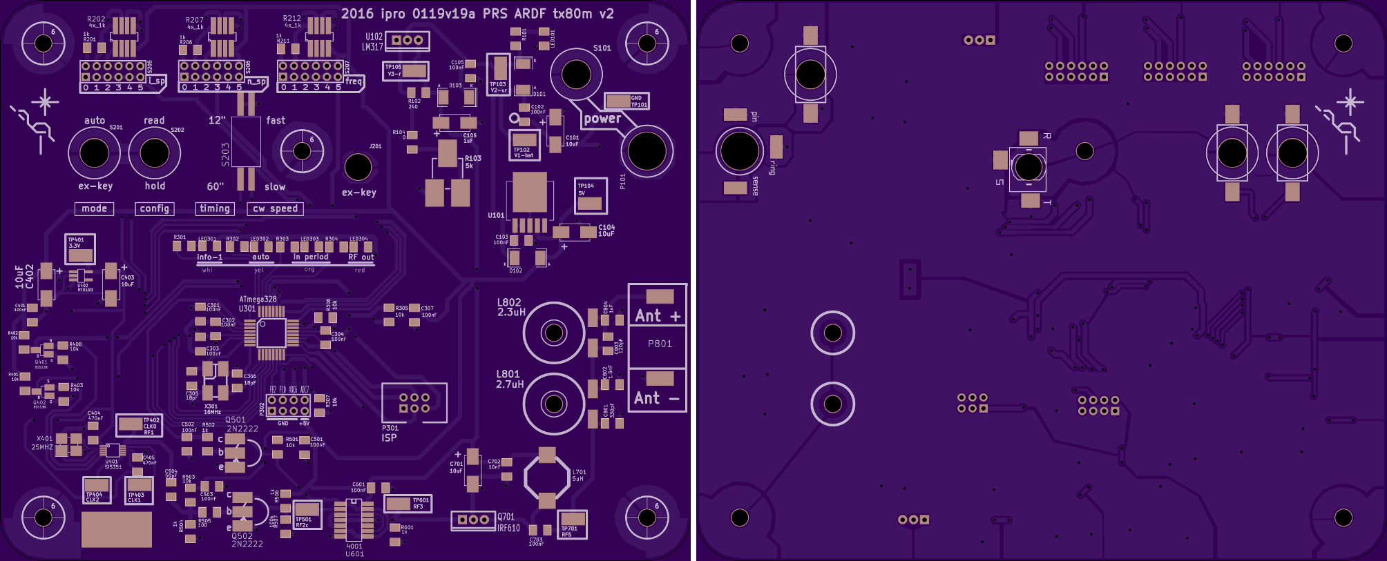
OSH Park PCB. The top is on the left the bottom (bottom-view) on the right.
Here is a general overview. The 'flow' is generally from the upper right corner, leftward, then down to the lower left corner, and finally rightward. Most of the voltage regulation is in the upper right. The battery wires will enter at P101 via a barrel connector. U101 generates 5 V needed by most components and U102 generates the regulated high voltage for RF output. Then the user input in the upper left. There are configuration inputs are those labeled: i_sp, n_sp, freq, mode, config, timing, and cw speed. At the label 'ex-key' (J201) there is a jack for manually keying the transmitter. Below all this and toward the center sits the ATmega328 controlling everything. Also there are a row of informative LEDs labeled info-1, auto, in period, and RF out. In the bottom, the RF is generated by the Si5351 at the far left and ends at the antenna pads at the far right.
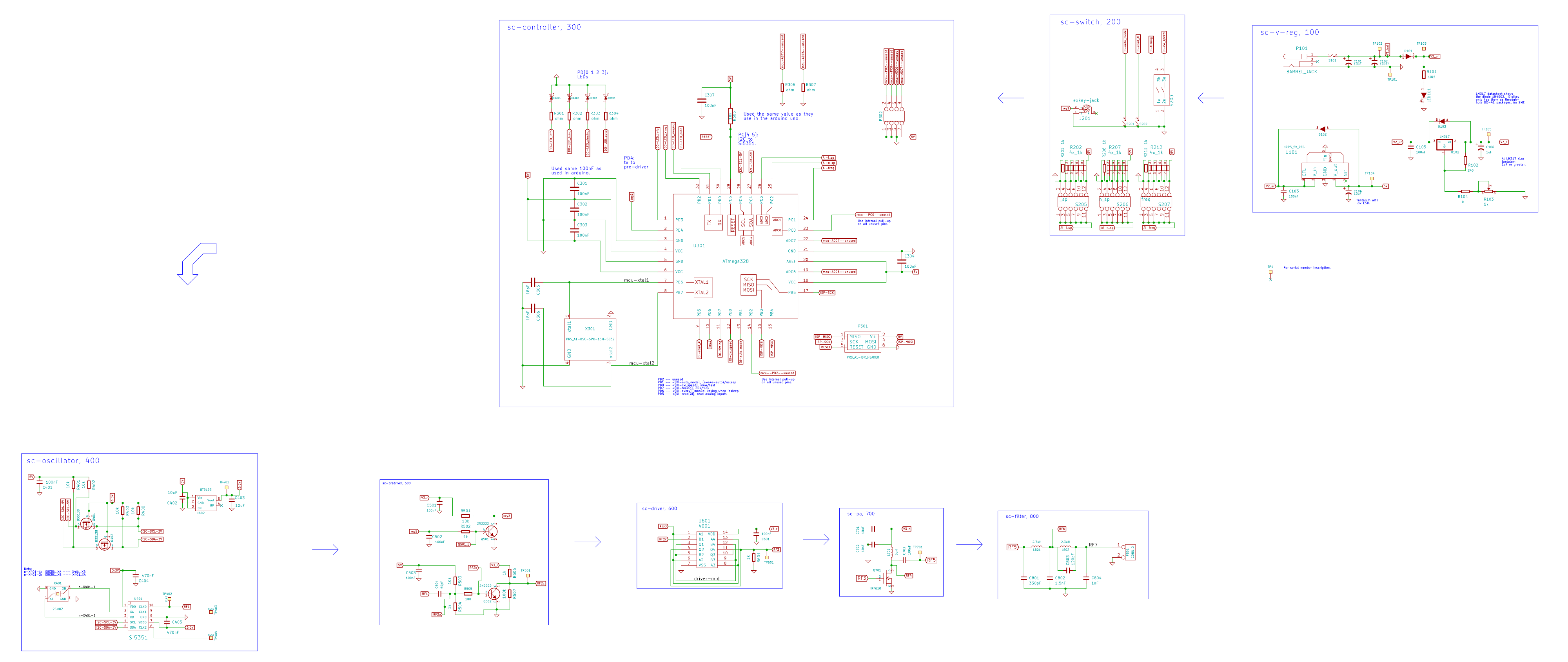
The schematic follows the same general pattern as the PCB. To see it all clearly, you should download the large file. In the future, I'll make a block diagram and break the schematic file into individual modules.
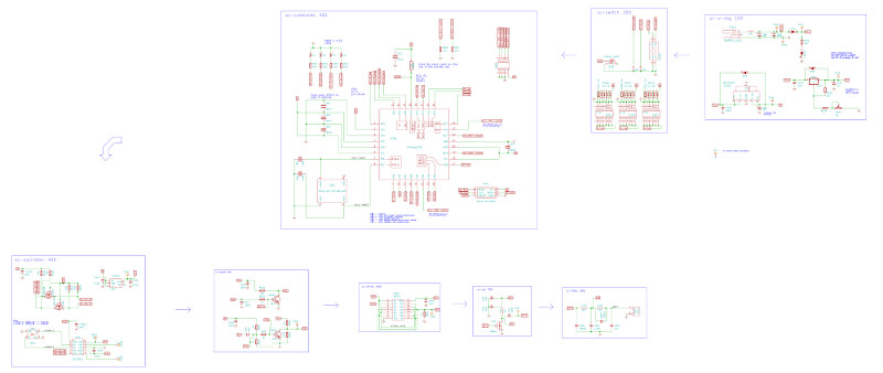
Schematic for version 2.
Full size (479 kB).
Looking at the schematic, you'll see how it is devided into a number of functinal modules: voltage regulator, switches (user input), controller (ATmega), oscillator (Si5351), pre-driver (2n2222), driver (4001), power amplifire (IRF610), and filter.
Coming updates
Images to put up next: layout-1-front, lyout-2-back--front_view.
Then I'll put up some information and images related to the mechanical building. That should be pretty fast. Then the BOM. At this point, there should be enough information for anyone to build it.
Programming it will come next. I have working code that was tested with every part of the transmitter. But I don't have a single program that has all the code in it. For now, the main program I'm using is enough to run a regular event, but not a sprint as I don't have the fast cw in there. As soon as I have it cleaned up, I'll put up at least that.
Since we now have working transmitters, the emphasis has been shifting away from development and building to actually getting out there in the woods. So the full version of the code may not go up for a while. But eventually (Fall 2016 maybe), I'll get back to the code and put a full version up.