--- PRS xp boards doc ---
2020-11-29
2020 ipro 1129v06a.
This list is here to help me find my boards visually
and have quick reminder of what they are.
Back to projects main page
Summary.
There are two sections,
one for single component boards and one for multi component boards.
Boards with more documentation available here use this font at the start of the legend.
UNDER CONSTRUCTION.
More coming... Pictures... Sometime... When I get to it... I hope...
List - single component boards.
Boards listed in order of size.
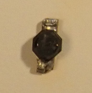
Fig: inductor breakout. 14x4 mm = 56 mm2.
In 2017 it was part of the !600-a3 tx2m board.
At that time it connected the base of the RF amplifier to gnd.
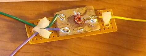
Fig: Transformer mini-module.
53x9 mm = 477 mm^2.
From 2017 ipro 1124v21b.
I'm pretty sure it's the transformer from Rik Strobbe's (ON7YD) 144MHz ARDF transmitter.
Check out 2017 ipro 0120v05c for the place where I think I first built it.
After it was built, it was placed on the experimental tx2m output filter board.
But then it was taken off again.
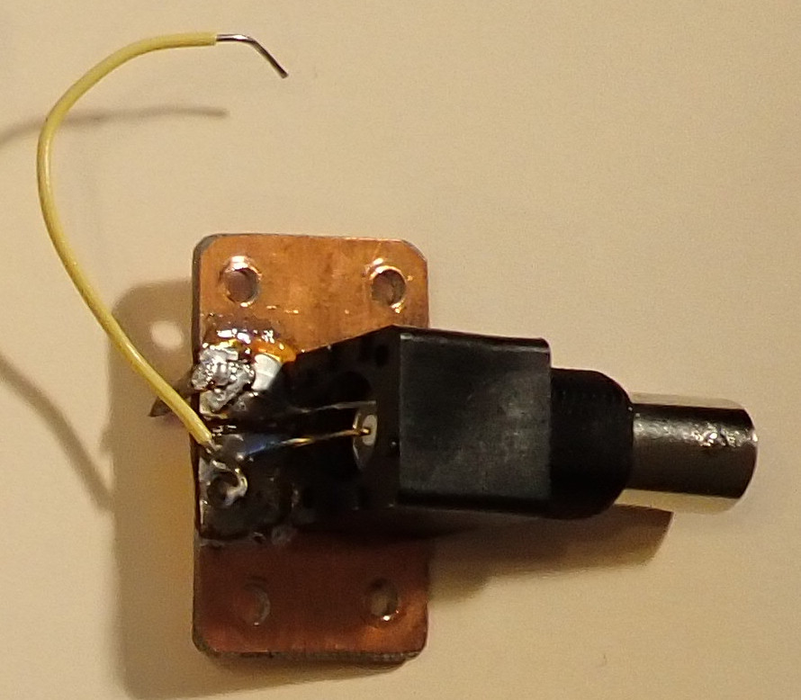
Fig: BNC breakout. 35x21 mm = 735 mm^2.
In 2017 it was part of the !600-a3 tx2m board.
It was the main output jack.
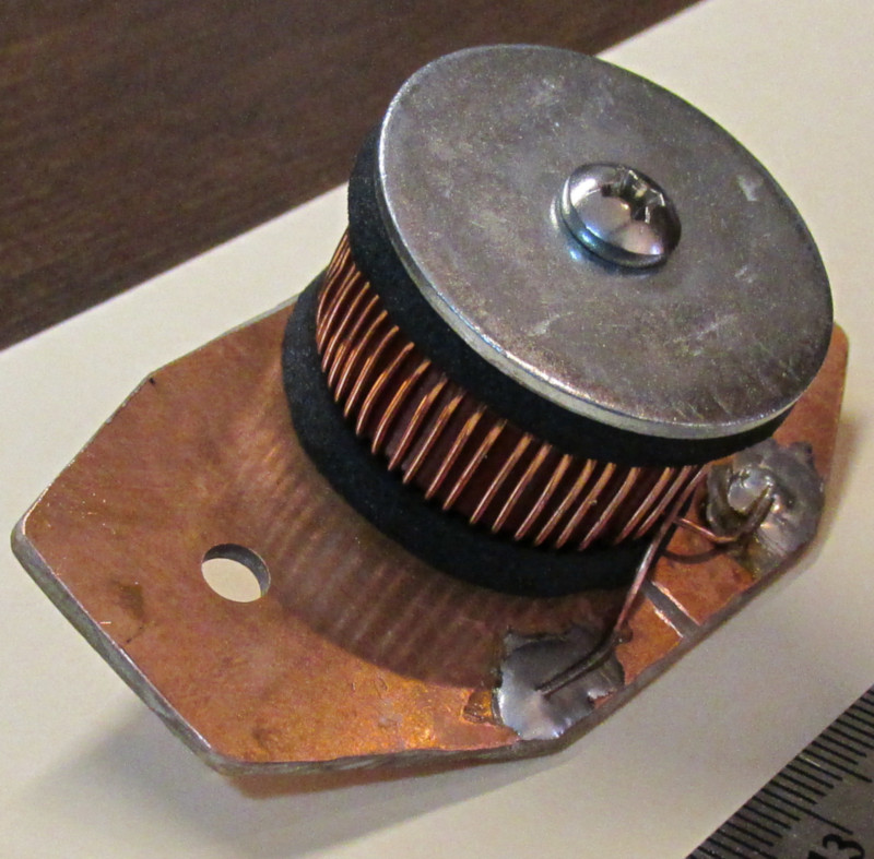
Fig: Breakout toroid inductor, 46 uH.
71x31 = 2201 mm^2.
2015 ipro 0522v17a.
T106-2 core, iron powder, #2 red, A_L = 13.5 nH/(turn^2).
R = 0.6 ohm.
55 turns. 22 AWG enamel coated wire.
Approximate wire length per turn = 3.54 cm/turn.
List - multi component boards.
Boards listed in order of size.
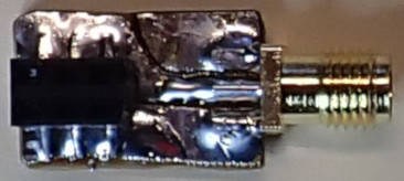
Fig: prsb SMA to rect fem header breakout.
19x12 = 228 mm^2.
Handy for testing output impedance of boards with SMA connectors.
2020 ipro 1218v05a.
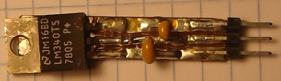
Fig: Breakout 7805 voltage regulator, 5 V.
38x8 = 304 mm^2.
2014/stidp-7de/electronics/c17s06a...
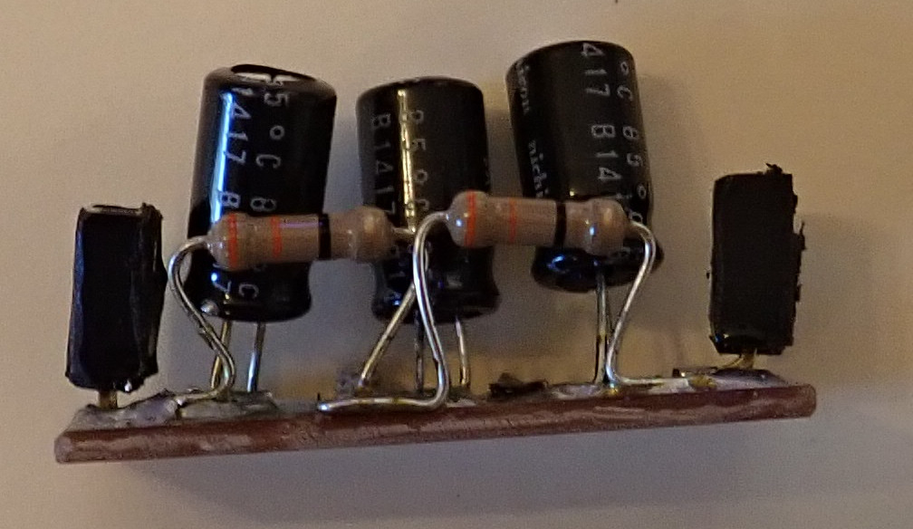
Fig: Low pass filter.
36x13 mm = 468 mm^2.
In 2017 it was part of the !600-a3 tx2m board.
It's an RC filter that was used to try to smooth out an AF square wave.
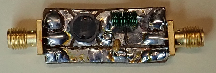
Fig: cxxe001.
prs DD AF4, low pass filter.
34x15 mm = 510 mm^2.
DOC.
It's a low pass filter to allow AF to pass to the RF chain and do modulation without RF going back into the AF boards.
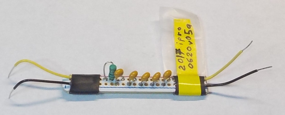
Fig: prsb AF filter 2017.
64x8 mm = 512 mm^2.
A low pass filter.
See 1129v06b--prs_made_xp_board_pics/ au1203c_prsb_AF_filter/ for a small write-up.
Originally from 2017.
I had built an RC low pass filter (from a David Deane schematic)
and then decided to replace the resistor with an inductor.
The LC circuit is only a second order filter and currently uses 1mH and 1.1uF.
The cut-off frequency {fc = 1 / (2 π sqrt[LC])} comes out to 4.8 kHz.

Fig: Attenuator. 48x21 = 1008 mm^2.
2020 ipro 1126v14a.
Made to attenuate the signal coming from a handy talky.
It didn't work too well at 146 MHz.
It will be interesting to test it at lower frequencies.
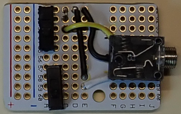
Fig: !877. TRS switcher.
(42x28) mm^2 = 1176 mm^2.
It's handy for plugging in a key line and closing either the tip or the ring to the sleeve
so that the output of a cw transmitter can be recorded.
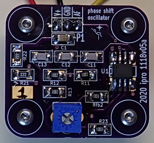
Fig: !635-b1-1. Phase shift oscillator.
(36x33) = 1188 mm^2.
DOC.
See 2020 ipro 1122v05a.
Note the board is incorrectly marked "ipro 1118v05a".
This was the first phase shift oscillator OSHP board to be built.
The plan is to test it as an AF generator to modulate tx2m RF.
It creates a nice sine wave, 640 Hz.
The U1 is a dual op-amp with the second op-amp used to buffer the output.
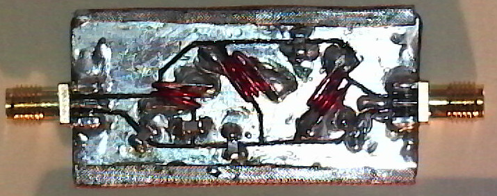
Fig: !1081-a2 - RF output filter for 2m band, from Joe Moell.
52x26 mm = 1352 mm^2.
See 2020 ipro 1205v09a.
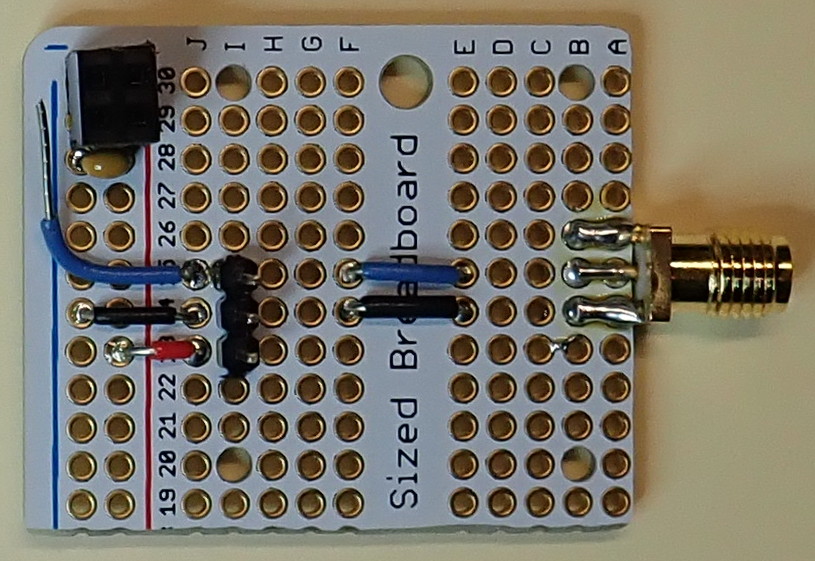
Fig: Handler for !635-b1 phase shift oscillators.
(41x34) mm^2 = 1394 mm^2.
DOC.
See 2020 ipro 1216v06d.
This board provides an SMA connector for the output of the oscillator board.
This makes it easier to connect the oscillator board to some other boards.
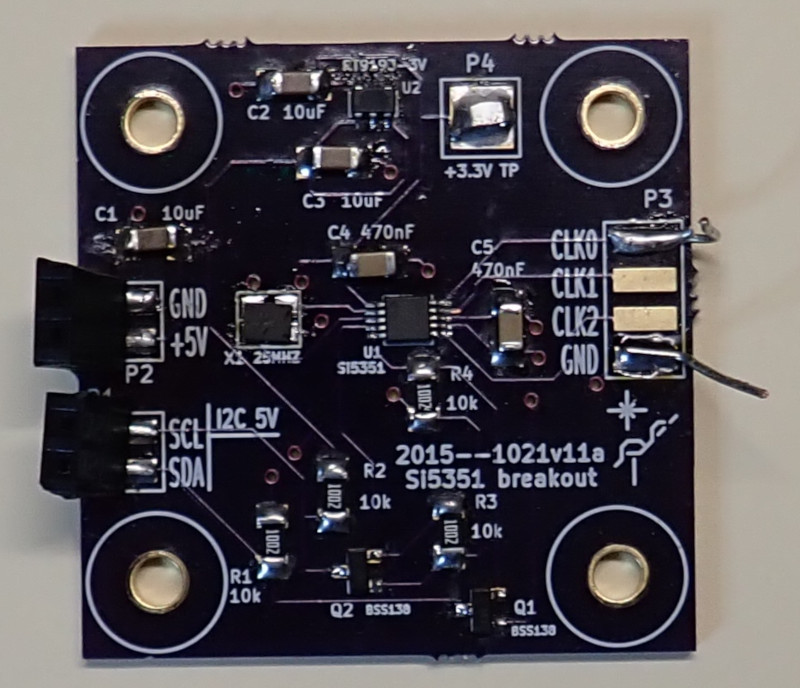
Fig: prsb si5351 (2015).
40x40 = 1600 mm^2.
This was originally part of the 2015 prs ardf tx80m "by-OSHP-module" project.
I took it apart on 2020-12-11.
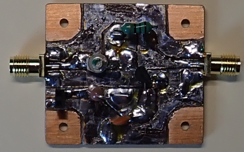
Fig: prsb tcvr40 rx switch.
44x39 = 1716 mm^2.
2020 ipro 1212v10a.
Build and initial test were on 2020-12-12.
From the David Rutledge book.
Uses a transistor switch to protect the receiver part of the transceiver.
In the first test, the switching function worked ok but the loss through the circuit was quite high.
Or was it?
The output was to a 50 Ω load and the input might be a high impedance.
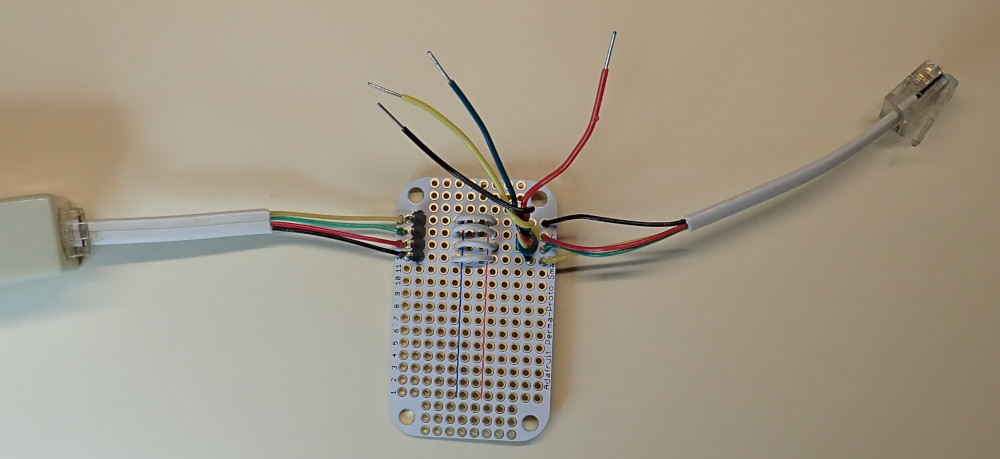
Fig: prsb 6P4C (RJ connector type) tap.
53x33 = 1749 mm^2.
This board is from a long before this year, 2020.
I think I made it to sniff the lines going between the telescope motors and the controller.
cxxe002.
53x33 = 1749 mm^2.
prsb tank and amp for 2m.
Originally from 2017 ipro 1016v05a--tx2m_stage_RF2.
---
Part of description from before latest alteration.
There are documentation annotated pictures and a schematic in that ipro.
It's has a tank at the input followed by an amplifier.
I'm pretty sure the transistor is a 2N3866 (!418) that I had picked
as a possible replacement for Rik Strobbe's BLU86.
But I think the basic design came from David Dean's circuit immediately
following the ICS-525 output.
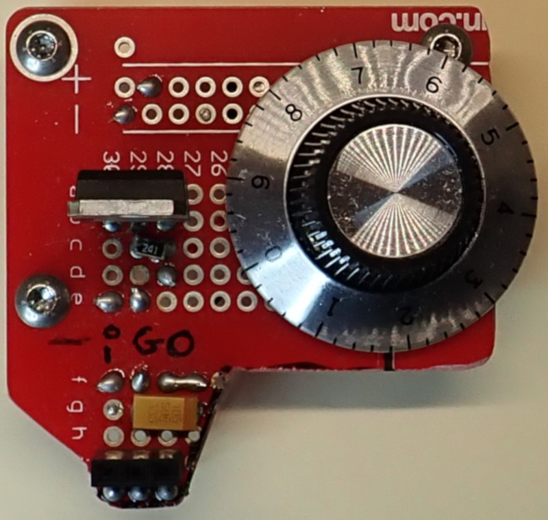
Fig: !410. LM317 variable voltage regulator.
(47*46) mm^2 = 2162 mm^2.
There are two identical boards.
The markings "I G O" identify Vin(unregulated) GND Vout(regulated).
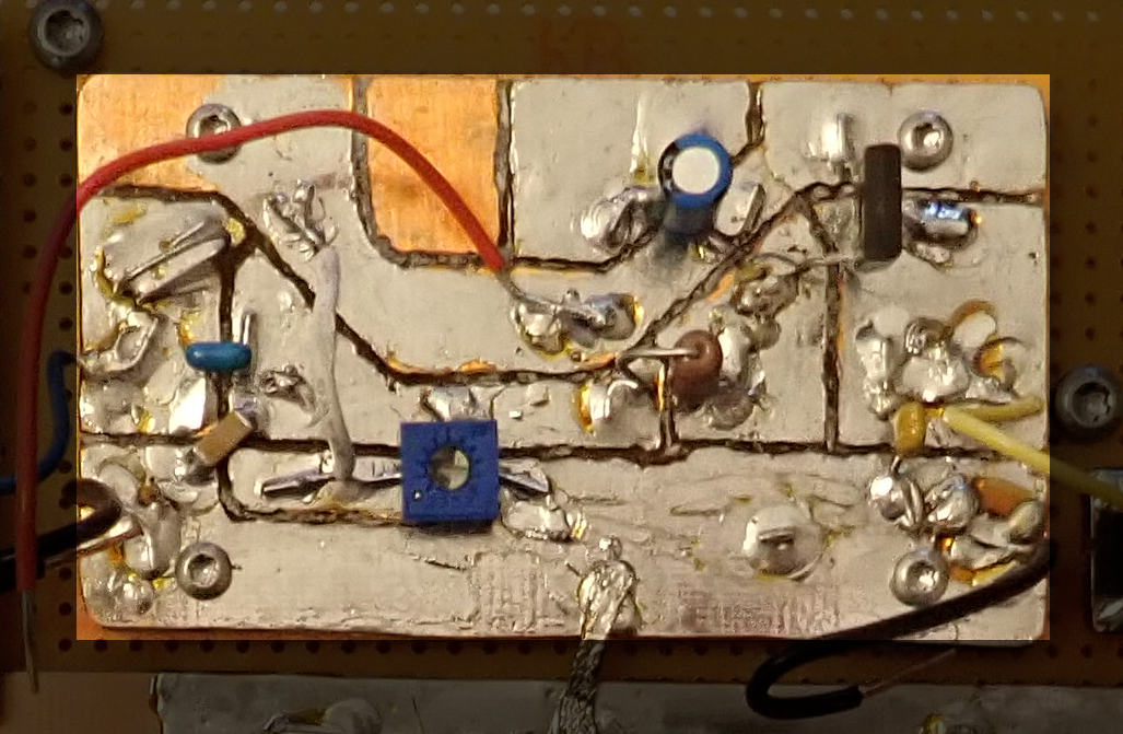
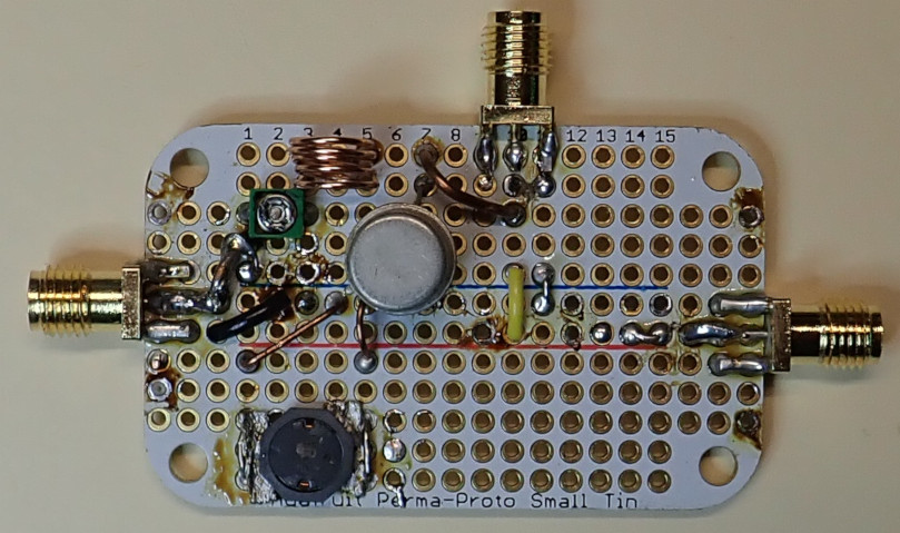
Fig: PRS RS tx2m AF section 2.
69x40 mm = 2760 mm^2.
This board was originally made working in 2017 ipro 1124v05a.
At the time, I was trying to combine Rik Strobbe and David Deane tx2m designs.
See 2020 ipro electronics--prs--ardf--tx2m 1130v05a--prs_RS_tx2m_ambi_board_2_spice for a more in-depth understanding of this board.
It's basically an amplifier using a PNP but it's not linear.
The input is at the left via a blue wire.
The output is the yellow wire at right.
In the RS circuit, it was powered by 12V (red wire here).
The input signal (blue wire) should probably be Vpp 5V sine wave.
See also cnotes from 2020-11-30 in 1130v05a ipro.
In there I did some quick hardware tests replicating the LTspice simulations.
Using an upward pointing axis, rotating the pot left-handed turned on the PNP while rotating it the other way turned it off.
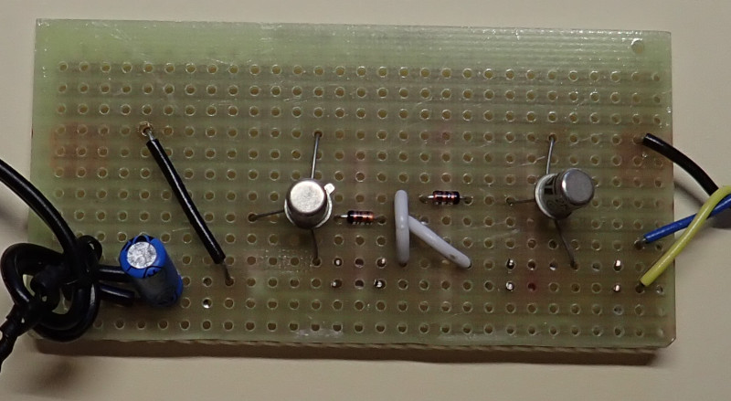
Fig: prsc !653-c1. AF generator.
76x38 mm = 2888 mm^2.
It uses two diodes and thwo 2n2222 to create a square wave.
Powered by 4V, it creates 707 Hz.
The blue wire output -2V to +2V, the yellow wire outputs 0V to +4V.
Originally created in 2018 ipro 1023v00a.
Altered in 2020 ipro 1129v06b.../au1129b.
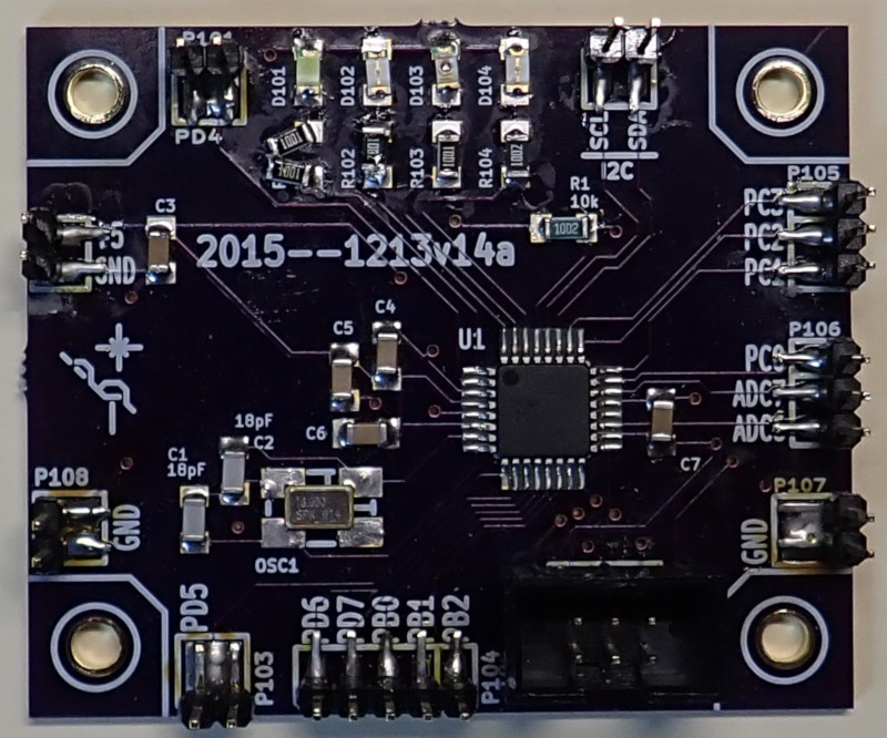
Fig: prsb atmega328 breakout (2015).
(60x50) mm^2 = 3000 mm^2.
This was originally part of the 2015 prs ardf tx80m "by-OSHP-module" project.
I took it apart on 2020-12-11.
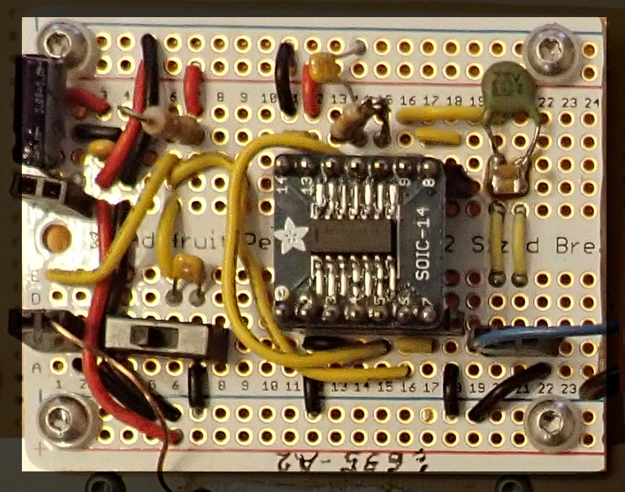
Fig: AF generator prsc 635-a2.
64x51 mm = 3260 mm^2.
In 2017 it was part of the !600-a3 tx2m board.
Removed 2020-11-29.
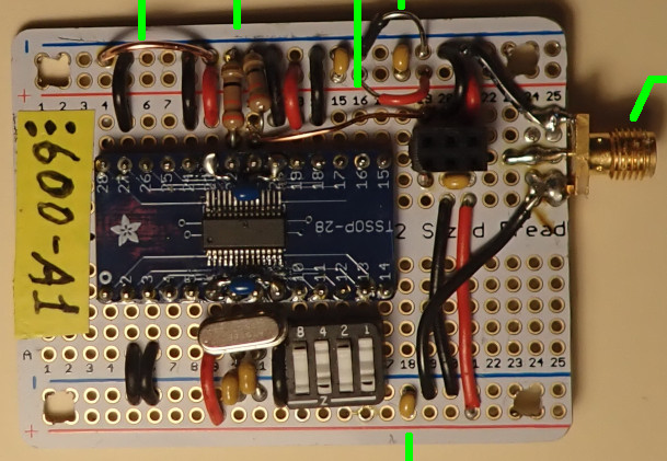
Fig: !600-a1. 66x51 = 3366 mm^2.
ICS-525 breakout.
Unlike the !600-a3, this one had no tank at the output.
2020 ipro 1127v14a.
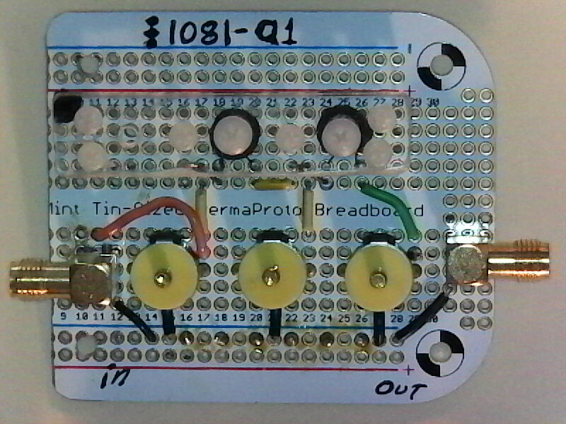
Fig: Output filter for 2m band transmitter, Rik Strobbe design.
64x57 mm = 3648 mm^2.
See 2020 ipro 1206v10a.
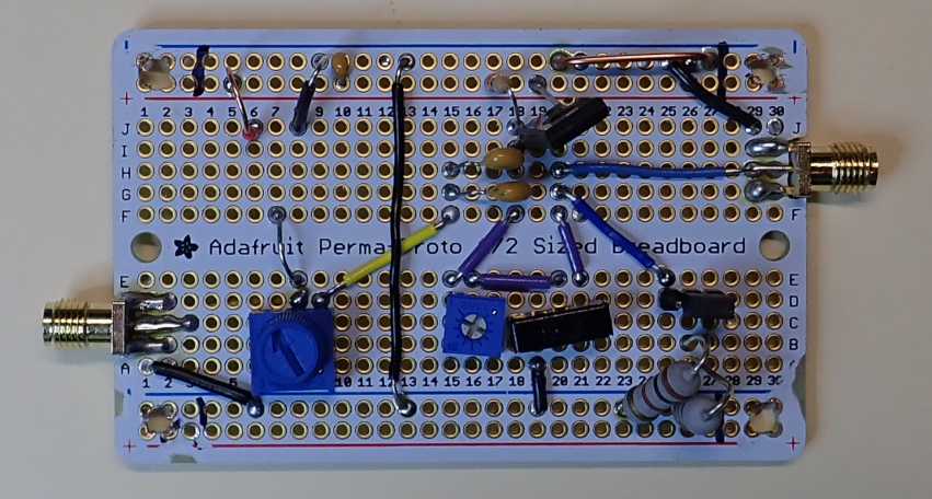
Fig: prsb DD AF13.
81x51 mm = 4131 mm^2.
DOC.
See 2020 ipro 1201v05a.
This is a version of part of the AF chain in David Dean's 2m ARDF transmitter.
In his design, it's the middle section that amplifies the AF.
Before it, he has the AF generation and filtering.
After it there is another filter that is mostly there to prevent RF from coming back into the AF section.
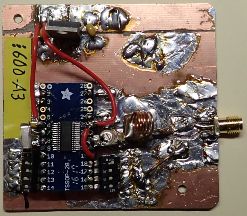
Fig: !600-a3. ICS-525 module.
73x70 mm = 5110 mm^2.
See 2020 ipro electronics--ics525
1127v14a--prsc_600_isc525_breakout_alterations.
This used to be part of a tx2m ugly construction until I cut it out in 2020-11.
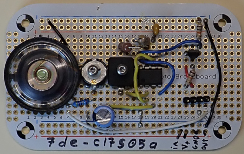
Fig: prsb 555 oscillator 7de-c17s05a.
(92x57) mm^2 = 5244 mm^2.
The 7de designation identifies it as a board from 2014.
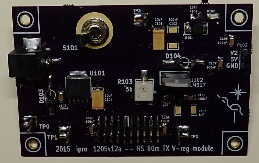
Fig: OSHP V-reg module for 2015 ardf tx80m, "by module" project.
90x60 mm = 5400 mm^2.
Repurposed for experiments since the "by module tx80m has been taken apart.
Original is 2015 ipro 1205v12a.
There is a picture of it as part of the tx80m project in the 2015 ipro 0103v05b.
It has two outputs, 5V and a variable output controlled by a pot and an LM317.
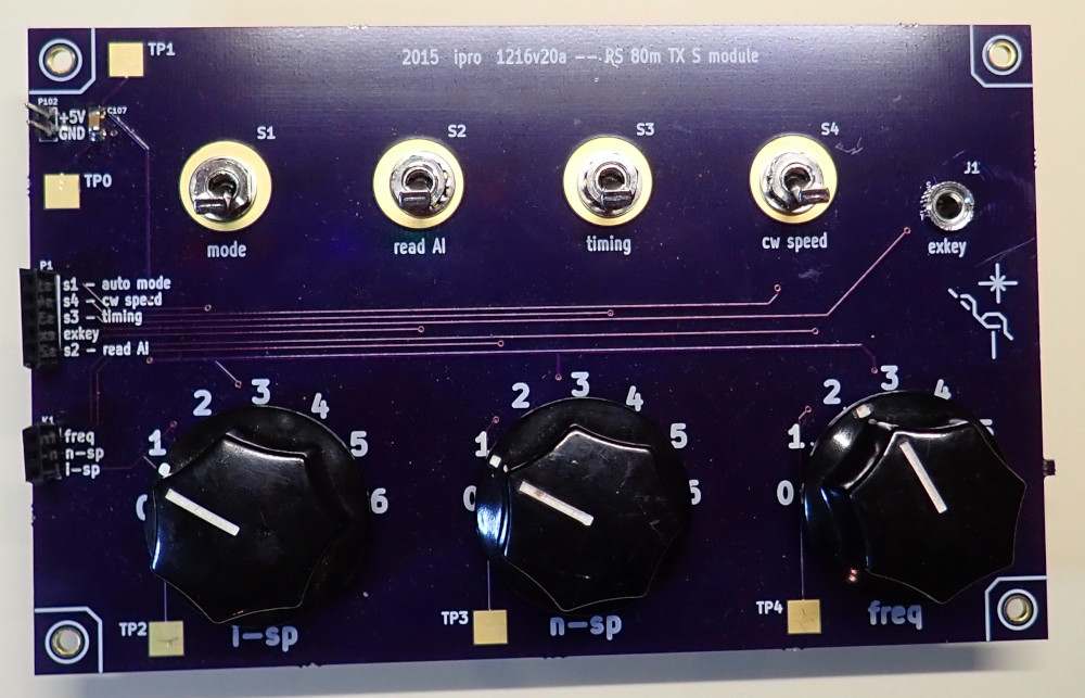
Fig: prsb tx80m input module ("S module", 2015).
(160x100) mm^2 = 160 cm^2.
This was originally part of the 2015 prs ardf tx80m "by-OSHP-module" project.
I took it apart on 2020-12-11.
It might still be useful for experiments because the three large 7-position rotary switches have their pins connected as a voltage divider.
Place holder section.
Empty section.