foxp
The CTS field box firmware.
Project location:
main_mseal/2019/ipro/
electronics--cts_course_timing_system/0303v17a--cts_field_box_software_foxp
Currently for version 005b being used in most field boxes
and 005d being tested.
Actually, this needs to be checked.
I think maybe 005d is being used.
Back to main doc.
What to expect during regular use.
This part is still not the same in all field boxes.
But we should make them all the same.
Generally, the fox is just turned on.
After a few seconds, an RFID card can be punched on it.
A beep signals that the field box thinks
a record has been successfully written to the RFID card
A subsequent beeps signal that a double punch of the RFID card
was detected.
In this second case, nothing new was written to the card.
The plan for the LEDs:
The yellow LED should be on when it's waiting to read an rcard.
Like that, we'll know that it's probably functioning ok.
While it's reading and writing, the yellow LED should be off.
If there was a successful write,
the box should beep.
If not, there should be no beep.
If some error is detected that is so serious it ends up in
the "halt" mode and is no longer functioning,
the red led should come on or maybe it should blink.
At that point, maybe we could use the yellow and red
blinking patterns to signal the error code.
Program flow - setup, main loop, and co_swipe().
In setup(), the following is done in this order.
If needed, the coco is written to the EEPROM.
The serial com is started (115200 baud).
The nfc lib is started to communicate with the RFID module.
Communications with the RTC is started.
Input pins {C0 C1 C2 C3 RTCreset} are configured as INPUT_PULLUP.
The LED pins and the Buz pin are configure as OUTPUT and all set to LOW.
If needed, the program goes into RTC reset mode and waits for input to reset the RTC.
After that, there is an alternate reset_RTC() function that can be called
if inPinRTCreset is low.
Finally, inPinC1 is check.
If it's low, the field box goes into BM_clear mode and clears any card that is punched.
In the main loop, it roughly goes through the following steps.
It set the yellow LED and calls check_for_card(), which is blocking.
It only returns from that call when an rcard has been punched.
So upon returning, it turns off the yellow LED.
The following action depends on it's mode, BM_control or BM_clear.
Assuming it's acting as a regular control (BM_control),
it calls co_swipe( coco, ut_now ) to write data to the rcard.
If the return is successful, it beeps.
Then it goes back to waiting for a new rcard punch.
Note that the main loop considers return values of 0 or 1 as ok and will beep.
Only return values of 2 or greater will stop a beep from occurring.
The co_swipe() function.
Roughly, co_swipe() does the following.
It reads the header; if fail it returns 2, no beep.
It checks for a double swipe.
Three conditions are required for a punch to be considered a double swipe.
First, the last rcard the box wrote to must be the same one being punched now.
Second, the rcard must report it's last coco as being the same as the field box's coco.
Third, a minimum delay must have passed.
If it's a double swipe, it returns a 1 and so there will be a beep.
It does some validation checks, returning 2 if an error is found.
It then authenticates and writes the record to the next position on the rcard.
Failure returns 2.
It then authenticates and writes the record to the header on the rcard.
Failure returns 2.
Finally it sets the last_uid_written_32 to the uid of the rcard and it returns 0.
Hardware configuration #defines
There are cts field boxes using this foxp software.
There are also master field boxes using different
software.
Each box has a number.
cts-1 (aka cts-1m) is a master.
cts-2, cts-3, and many others are field boxes.
Appart, for the box #, each field box has a control code
(aka cc or coco) burned into its eeprom during one of
it's firmware uploads.
The coco is the number that will be written to the rfid card.
There are a set of #define which are often changed to determine the hardware configuration:
-
acc.h: HW01_prototype / HW02_pcb -
What type of harware is being burned.
-
acc.h: WRITE_COC_TO_EEPROM -
Should a new coco be burned to the eeprom.
-
acc.h: DEFINED_COCO -
The coco to write to the eeprom.
-
acc.h: HAVE_DEBUG_CONSOLE -
Enables Serial.print() commands.
-
foxp005d.ino: RESET_RTC_MANUALLY_NOW -
Used during manual setting of RTC shortly after firmware upload.
-
xxx
These are all in acc.h and foxp005d.ino.
There are none that change often in p_rfid.h.
The two ways to reset the RTC.
System 1 requires flashing the hardware twice.
System 2 requires a serial monitor connected to the hardware to communicate with it.
System 1, summary.
This is the system I'm currently (2019-04-11) using.
In the foxp005d.ino setup() function,
uncomment the
#define RESET_RTC_MANUALLY_NOW
line.
A few lines below that, there is a place to type in a time
shortly in the future.
After flashing the software,
a switch can be used to tell the RTC when the time is now.
The software has to be reflashed when done
or moving that swith would cause the RTC to reset again.
System 2, summary.
In the foxp005d.ino setup() function,
shortly after the RTC System 1 code,
there is a function that checks the inPinRTCreset switch.
If it is low, the reset_RTC() function is called.
That function is defined in acc.cpp.
In it,
the code allows communication via the serial monitor
so the a new time can be entered.
I haven't used that system in a long time.
Details for RTC resetting System 2.
All the stuff in this section needs to be checked.
This system requires the field box to be connected
to a PC via a USB-FTDI cable and have the serial monitor running.
I'm pretty sure it won't work with direct USB-to-USB
because the serial monitor works with the Pro Trinket that way.
Setting switch 4 down (toward the TP3 GND pad) at startup
sends the code to the reset_RTC() function
defined in acc.cpp.
It then goes into a
while(1)
loop.
The only way it leaves that loop is by sending it an
x
via the serial monitor.
In the while(1) loop,
the following variables are involved in how the loop works.
| command | Possible values: 0 1. Starts at 0. Can be set to 1 by sending '='. Automatically resets to 0 with every pass through the loop.
Generally, append to sline when command == 0 and use single-character commands when command == 1. |
| sline | A string. While command == 0, anything sent other than '=' is appended to sline. |
| d_buf | Holds the date value that will be used to reset the RTC. |
| t_buf | Holds the time value that will be used to reset the RTC. |
| xxx | xxx |
Generally when command is set to 0,
any text sent to the field box is appended to sline.
Made a mistake?
Sending the command w clears the sline.
While in command 0 mode,
sending a single '=' puts you in command 1 mode
for a single pass and then goes back to command 0.
So a '=' needs to be sent before any command can be sent.
In command 1 mode,
the following can be sent to the field box:
| x | Exit the loop. |
| c | Print the date and time of the compile time of the firmware. |
| n | Print the current time reported by the RTC. |
| w | Clear the current sline. |
| l | Print the current sline. |
| ! | Reset the RTC using the current d_buf t_buf. |
| d | Translate current sline into d_buf and clear the sline. |
| t | Translate current sline into t_buf and clear the sline. |
| f | Print the field box's coco. |
| xxx | xxx |
Generally, the procedure for resetting the RTC goes as follows:
- Set the switch that will put the box into the while(1) loop and turn, turn on the field box, and plug it into the laptop.
The order needs to be checked here.
- Enter the date current date to copy it into sline.
- Enter '=' to go to command 1 mode.
- Enter 'd' to translate the sline date into d_buf.
- Enter the a time shortly in the future to copy it into sline.
- Enter '=' to go to command 1 mode.
- Enter 't' to translate the sline time into d_buf.
- Enter '=' to go to command 1 mode.
- Enter 'l' to see that the data w
- Enter '=' to go to command 1 mode.
- Look at a clock and wait for the selected time arrive...
- Enter '!'. This should reset the RTC.
- Enter '=' to go to command 1 mode.
- Enter 'n' to see and check the time reported by the RTC.
- Enter 'x' to exit the loop and go to normal operation.
- xxx
- xxx
d_buf and t_buf formats.
Using the example of 2018-04-13 07:30:00,
the text entered into sline must be as follows.
For d_buf, use
Apr 13 2018
.
For t_buf, use
07:30:00
.
Note that the following d_buf pariculiarity for single-digit dates.
If the date was 2018-04-09,
d_buf would need to be
Apr 9 2018
with two spaces between Apr and 9.
xxx
The #define HAVE_DEBUG_CONSOLE.
Still to be implemented to either implement or not implement
the serial print statements.
Hardware versions.
There are currently only two hardware versions:
HW01_prototype for cts-2
and
defined HW02_pcb for all other field boxes.
Which one is used is set in acc.h.
The only place this has a direct effect is in acc.cpp
where it changes the configuration of some pins.
The switches.
For all field boxes,
I have been designating switch positions as
(+) when the two switch side are disconnected
and a side connected to a Trinket pin will read HIGH
because of INPUT_PULLUP.
Then (-) closes the switch circuit and
connects the trinket pin to ground.
For normal operation, all switches should be in the (+) position.
A (-) position turns on a special software function on some switches.
In both hardware versions,
I number the switches starting with 0 on the side closest to the RFID module header.
Most field boxes (HW02),
have 7 slide switches {6 5 4 3 2 1 0} and (+) when pushed toward the LED side of the PCB.
The single HW01, cts-2
has 5 rocker switches {4 3 2 1 0} and (+) when the rocker is pushed down on the LED side of the PCB.
Note that these hardware versions HW01 and HW02
regard the field boxes that use foxp.
Currently these are cts-{2 3 4 ... 17}.
The masters cts-1m and cts-2m use different firmware.
Hardware -- config switches.
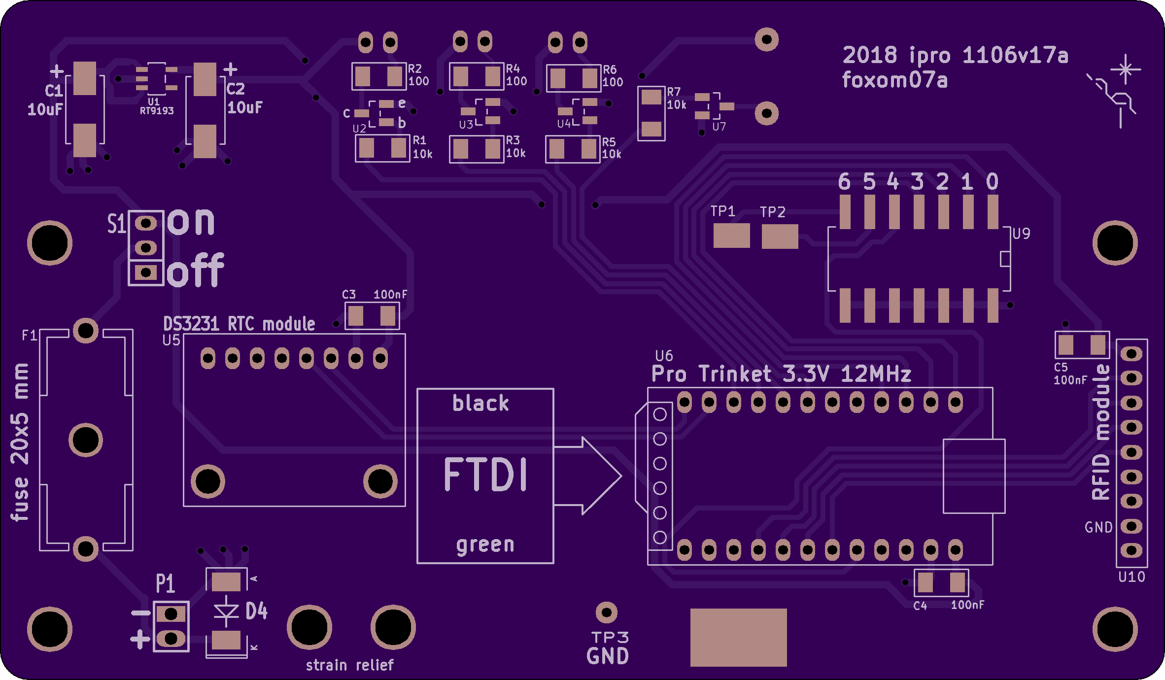
There are seven config switches, {6 5 4 3 2 1 0} as seen on the PCB.
All of them are connected to GND on one side.
On the other side, {4 3 2 1 0} are connected to Trinket pins.
Switch 6 is connected to the TP1 pad, switch 5 to TP2.
Only switches {4 1 0} are currently used.
|
|
The way the switches are soldered in on cts-5 and cts-7 (and on all?) field boxes,
pushing the switch toward the side with the TP3 GND pad connects the pin to GND.
So in the code, it would read "LOW".
The image is from:
main_mseal/2019/ipro/electronics--cts_course_timing_system/0226v00g--cts_2019_Feb_field_box_build/as01--materials/foxom07a_from_2018_ipro_1106v17a/s01--front.png
|
All the switches should be "up" for normal operation.
By up, I mean pushed away from the side of the PCB with the TP3 GND pad.
In up position, they are open and disconnected from GND.
In their configuration, they are all set to INPUT_PULLUP.
So they will all read HIGH.
| switch number | code designation | notes |
|---|
| 0 | inPinC0 | LOW: Start RTC reset system 1. |
| 1 | inPinC1 | LOW: Set box_mode to BM_clear. |
| 2 | inPinC2 | No function. |
| 3 | inPinC3 | No function. |
| 4 | inPinRTCreset | LOW: Start RTC reset system 2. |
| 5 | none | TP2 |
| 6 | none | TP1 |
The switches are only read in setup().
The switch that is used for resetting the RTC is still in use.
There is also one new function in foxp version 005d
using a switch to set the mode to either regular control or clear box.
This hasn't been well tested yet.
The other switches are currently not being used.
These used to be used for setting the field box's control code (coco).
But that was changed.
Now the coco is set at flash time by burning it into the EEPROM.
It's nice to not have to flash the field boxes to change
their configuration.
In the future,
it may be handy to write a function to use a switch
that will allow setting of the coco using a serial monitor.
We're using Trinket software.
If it goes out of date, it may be difficult to flash field boxes.
But the ability to communicate with them using an FTDI/USB cable may last longer.
Switches 5 and 6, TP2 and TP1.
These switches are connected to GND on one side and to their respective TP pads on the other.
So they have no connection with the reset of the circuit.
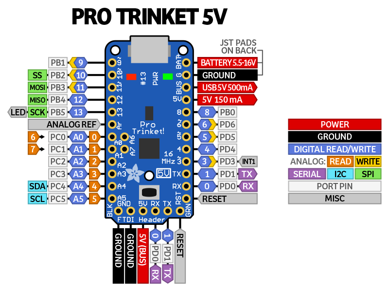
But the trinket has two t-h pads that are not on the edge.
These are pads A6 and A7.
They currently have nothing soldered on.
In the future, we could solder wires from TP2 and TP1 to these pads and control the input using switches 5 and 6.
|
|
The image shows the Adafruit Pro Trinket 5 V.
But the 3.3 V version has the same pinout.
Note the "internal" pins A6 and A7.
File source on Adafruit website.
|
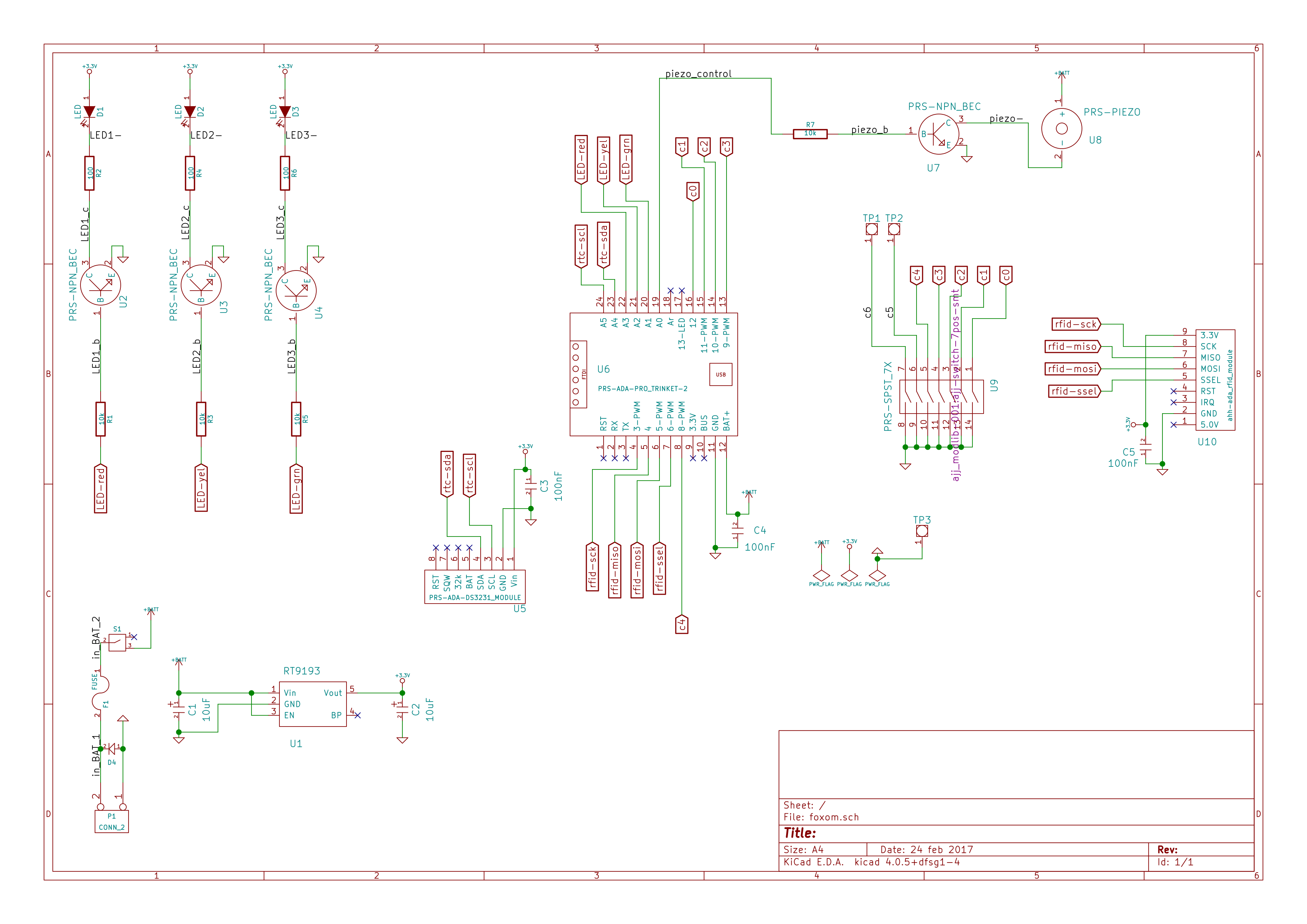
The schematic.
|
|
The original file:
main_mseal/2019/ipro/electronics--cts_course_timing_system/0303v17a--cts_field_box_software_foxp/as01--versions/foxp005d-doc/doc_html/images/foxom_schematic.png
|
The green LED.
We're not planning on using the green LED anymore.
All the hardware has connection to put on the green LED.
Not all hardware have the green LED soldered on.
But since some do have it soldered on,
we still need to make sure it is configured as an output and set to LOW.
Flashing.
Use Adafruit custom arduino IDE.

On my systems, this is installed so that it can
be started by typing
  trinket
at the command line.

Arduino settings needed:
  Board:         Pro Trinket 3V/12MHz (FTDI)
  Programmer:    USBtinyISP
  Serial Port:   ttyUSB0, ttyUSB1, ...
  Serial rate:   115200
Flashing - The first time.
The following is taken from the file
compiling--first_load_of_new_field_box.txt
and may be a bit out of date.
From cnotes 2018-11-21 Wed, using cts-3(coco-32) as
an example...

Important:  In acc.h, set the hardware version to the
correct setting for that field box.  E.g.:
---------------------------------
#define HW01_prototype
// #define HW02_pcb
---------------------------------


--------------------------------------------
We will go through a similar sequence with every
newly build field control box.  It does two things:
- It sets the box's unique coco (control code).
- It sets the box's RTC to the current UTC time.
--------------------------------------------
The sequence for cts-3:
--------------------------------------------
- 1.  In acc.h, set the coco defines:
        #define WRITE_COCO_TO_EEPROM
        // #define DEFINED_COCO 0
        #define DEFINED_COCO 32
- 2.  Bring up a UTC clock and decide on a time
      a couple minutes in future to write in
      the code.
- 3.  In foxp###.ino, set RTC:
        #define RESET_RTC_MANUALLY_NOW
        ...
        rtc.adjust(DateTime(
          F("Nov 21 2018"),
          F("13:45:00")
          ));  // *** change as needed
- 4.  On PCB, push C0 pin (labeled "0") to low,
      away from "star-crane".
- 5.  Load the code.
- 6.  Wait for the UTC clock to reach the desired
      time and push the C0 pin high, toward star-crane.
- 7.  Push C0 back to low pos.
- 8.  In acch.h, reset #defines.
        // #define WRITE_COCO_TO_EEPROM
        // #define DEFINED_COCO 32
        #define DEFINED_COCO 0
- 9.  In foxp###lino, reset #defines.
        // #define RESET_RTC_MANUALLY_NOW
--------------------------------------------

* Some of the order of pin settings may change
  in future and already is a bit different for
  the two field boxes.
  - See cnotes 2018-11-21.
Possible new burn procedure:

- 1.  Set switches to
        6 5 4 3 2 1 0
        + + - + + + +
      where
        + = up   = away from TP3 GND pad.
        - = down = away from TP3 GND pad.
      Having 4 in down position will put it in
      a re-configuration mode.
- 2.  Turn on and connect to PC with USB- cable.
- 3.  Upload the firmware.
- 4.  When upload is done, hit ctrl-shift-m in IDE
      to bring up the serial monitor.
      - Wait for it to go into the re-configuration
        mode.
- 5.  Assuming we want to set it for
        coco 42
        2019-04-13 17:00:00 UTC
      In the serial monitor sending area, type the
      following:
        42=g
        Apr 13 2019=d
        17:00:00=t
      Look at a clock and wait.  At exactly 17:00:00,
      hit .
- 6.  Disconect the field box and turn it off.
- 7.  Set switches to all up:
        6 5 4 3 2 1 0
        + + + + + + +
- 8.  - Put red tape on the swipe area with 42
        written on it.
      - Put blue tape on it with firmware version
        and burn date on it.