089. Instructions for 80 m transmitters to use on April 21.
2018-04-19. Patrick.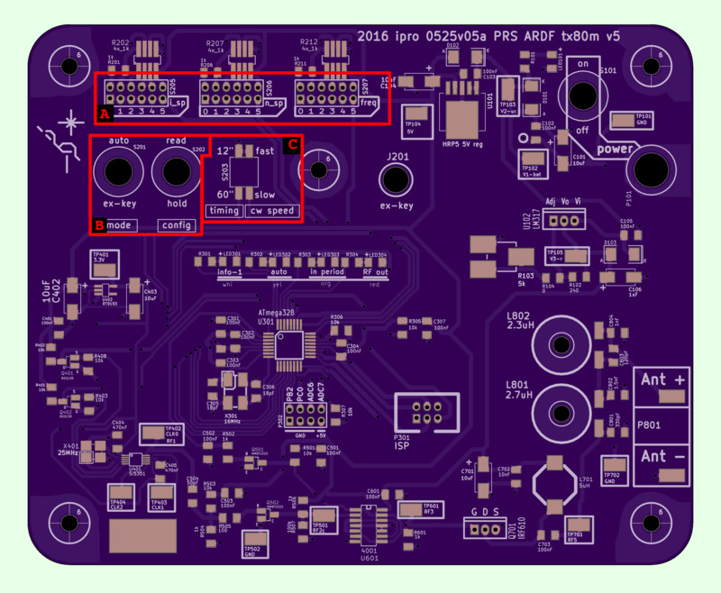
Fig. 1. Main transmitter layout. The switches with changed functions are labeled A, B, C, in red.
Summary/reminder list.
- S206/n_sp now controls the delay before the transmitter starts sending RF.
- S206 positions, left to right: no delay, 30', 1h, 2h, 3h, 4h.
- The mode switch must be set to "auto" to actually send RF.
- For classic events, S203 (timing and cw speed) switches should both be in the down position.
- The red LED will flash according to the timing but this doesn't mean RF is actually being sent to antenna jacks.
- The white LED flashes along with red LED when RF is actually being sent to antenna jacks. Ie when the transmitter is in auto mode and any delay has passed.
Intro.
This blog post describes the changes in 80m transmitters functions caused by recently flashed firmware. It's mostly for Joseph who will be using the transmitters on April 21 but also as a record.
Figure 1 shows the layout of the transmitter board. The three main areas where switches have changed functions are labeled A, B, C and have closeups below.
Area A switches. (Fig. 2)
This area has three sets of jumpers S205, S206, S207. Each of these sets should have one and only one jumper on it. These are not switches, they are voltage dividers. The jumper on each one, sends the appropriate voltage level to a pin on the microcontroller. Joseph, I had forgotten this when we talked last. There are 6 positions but it's not possible to get 26 values. Putting more jumpers on a set will increase the current going through the voltage divider and will eventually destroy the board. Using a jumper instead of dip switches allows me to use a single pin on the microcontroller. Wiring the voltage controller through dip switches would just make it too easy for someone to burnout the boards by flipping more than one switch on.
- S205 / i_sp
- Sets the fox id, 1 2 3 4 5. 0 for homing beacon.
- No change here.
- S206 / n_sp
- This controls the delay between the transmitter being turned on and RF being actually sent out.
- setting/delay duration: 0/no delay, 1/30', 2/1h, 3/2h, 4/3h, 5/4h.
- This used to control the number of foxes. Ie the duration of an entire cycle through all foxes present. There is no longer a way to change the number of foxes. It's always 5.
- The delay used to be controlled using jumper set P302, next to the microcontroller. That jumper set is no longer used.
- Most of the transmitters were left with a 2h delay at the end of the Apr-15 event. But one of them had no delay. Can't remember which one. And the homing beacon was probably left with the 30' delay.
- S207 / freq
- Controls the RF frequency.
- No change here.
Area B switches. (Fig. 3)
The mode switch. The function of this switch hasn't changed much. Basically, think of it as "auto" mode being either on (switch up) of off (switch down). If the transmitter is in auto mode and the delay has passed and it is in-period (in the appropriate period for it's particular fox ID), it will transmitter RF. It's ok to turn on the transmitter with the mode key already in auto position. This means that the transmitter can be turned on and closed up at home and never opened up again until its time to turn it off. In theory, the final should be able to handle having no antenna hooked up to the RF jacks. But I haven't tested this. So I would rather not have the transmitters turned on in auto mode if there is no delay and no antenna connected. One thing that has changed is that switching the mode from auto to ex-key no longer sends the call sign one last time. I need to work on a system to handle this.
The config switch. This is no longer functional. It used to allow the re-reading of the configuration after the transmitter had been turned on. Now, the configuration is read when the transmitter power is turned on. Any change in the configuration will require turning the power off, waiting for the appropriate time for the transmitter to be in sync with the others, and turning the power back on. Sorry.
Area C switches. (Fig. 4)
These now work but the labeling is incorrect. The labels should be switched left to right for the way it's currently functioning. In the future, I'll probably change the code so that the switches work the way the PCB is labeled.
Left side switch. It currently functions as the cw speed speed. It only has an effect if the transmitter is in sprint mode. With the left side switch down, the code speed is slow. With it up, it's fast.
Right side switch. It currently functions to control the period timing to cycle through all 5 foxes, either 60 seconds or 12 seconds. With the side switch down, the transmitter is in classic mode (60 seconds on, 4 minutes off). With the switch up, the transmitter is in sprint mode (12 seconds on, 48 seconds off).
LEDs work differently.
It used to be that the red LED flashed the same as the RF being keyed. This would only happen when the transmitter was in auto mode and any delay had passed. Now, we can see if the transmitter is timing itself correctly at all times. The red LED flashes as if it were in auto mode and there was no delay. But RF is only actually being sent to the antenna jacks if the white LED also flashes at the same time.
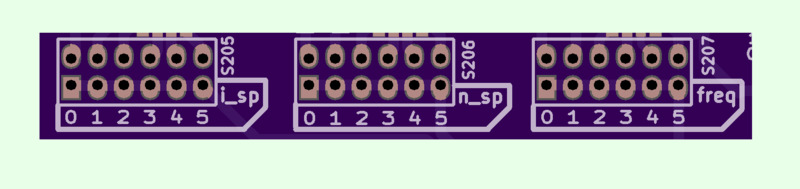
Fig. 2. Area A switches. Only S206 / n_sp has changed. It now controls the delay. There is no longer a way to control the number of foxes. It's always 5.
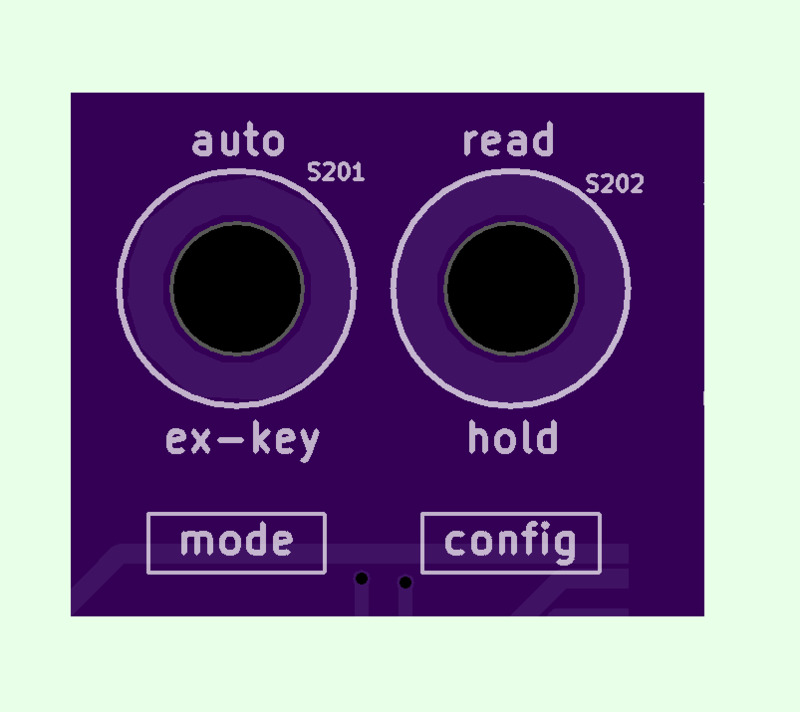
Fig. 3. Area B switches. The mode switch functions mostly as it used to. The function switch is no longer functional.
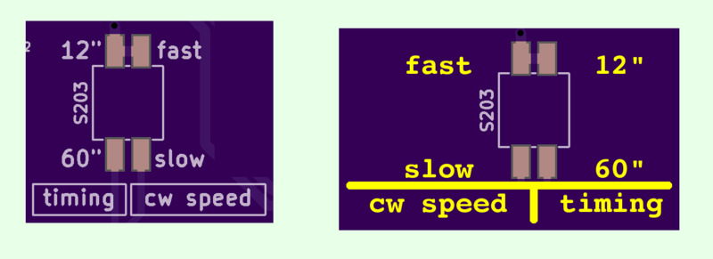
Fig. 4. Area C switches. The left panel shows the PCB labeling. The right panel shows how the transmitter actually reads these switches. The label timing refers to classic (60 second on) versus sprint (12 seconds on) timing. The label cw speed refers to the morse code speed and only has an effect if the transmitter is in sprint mode.