088. IsCT news - First outdoor tests of the new ARDF 2 m transmitters.
2018-02-03. Patrick.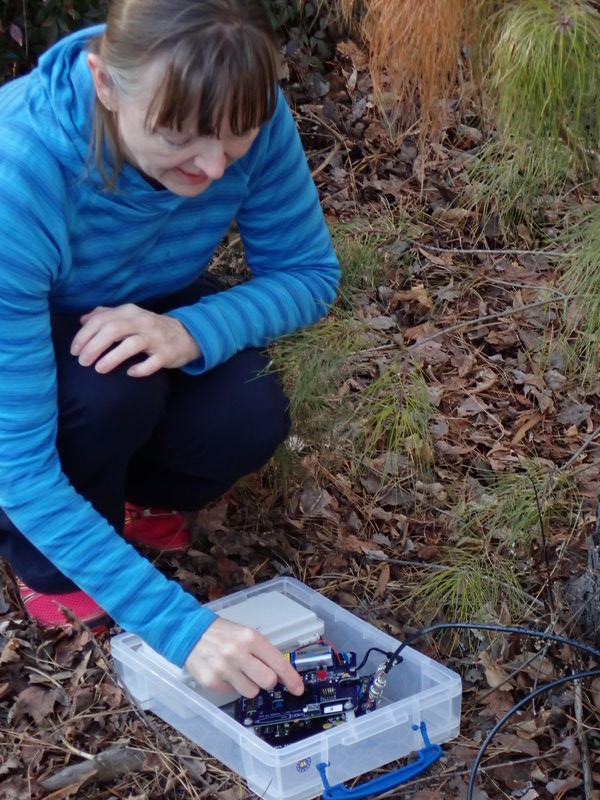
Fig. 1. Kelly powering down the transmitter. At that moment, she was switching the transmitter to manual mode before shutting off the power. This is a happy moment. We finally know these will work.
We've had great progress in the last month. For the first time, we have an RF PCB that works and an controller PCB that works. The code has been adapted to these new boards. We have our first antenna and feedline built. And for the first time, we built the new type of battery pack that will power the 2 m transmitters. Today was the big test. Our first test of the whole system put together outside, getting out a receiver, walking away and finding out if it will work. Success! Happy day! ☺
Here follow a few pictures from our happy day.
Some notes about Fig. 2 and our powering solution. We'll be using an external battery pack. We'll want to sync the transmitters before putting them in the course setting backpack. But at that time, we won't want to plug the external packs into the transmitters. So that's what the 9 V size battery is for on the controller. It keeps it going until we get out in the field and place the transmitter at its final location. At the time, the main battery pack takes powers both the RF and controller boards. The battery pack will have 12 C-size NiMH cells. We're almost certainly going to adapt all the 80m transmitters to use the same system. The voltage will be lower and so much less will be wasted at the voltage regulator. Also, the capacity of the cells will be double (nominally 5000 mAh instead 2500 mAh).
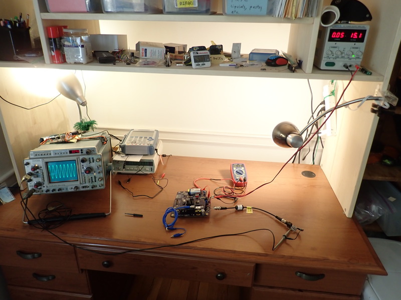
Fig. 2. First ever test where everything worked. Or at least enough to operate autonomously sending out ARDF codes with the correct pattern. The two OSH Park PCBs are on the table. The controller board on top has a 9 V size Li-ion battery directly on the PCB. The bench top power supply in the upper right is sending power to the RF board on the bottom. There is a blue stereo cable plugged into the key jack for testing manual keying. The RF output of the board (BNC to the right) goes into a short RG58 coax. The coax ends at a 50 ohm dummy where the oscilloscope probe is measuring the output. The oscilloscope at left is a Tektronix 475A with a bandwidth of 250 MHz. It's currently showing the waveform of the carrier. As far as we can tell, it looks like a clean sine wave. We'll do some more testing when we get better equipment.
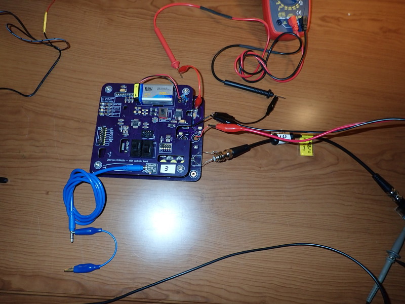
Fig. 3. Closeup of transmitter. Mostly we can see the controller PCB on top. Some pads are still unpopulated. The parts are on order but not essential for basic functionality. The blue cable is a stereo cable for testing manual keying. The 9V battery hooked up directly on the controller PCB. There plenty of cutouts so we can access the trimmers and control switches on the RF board.
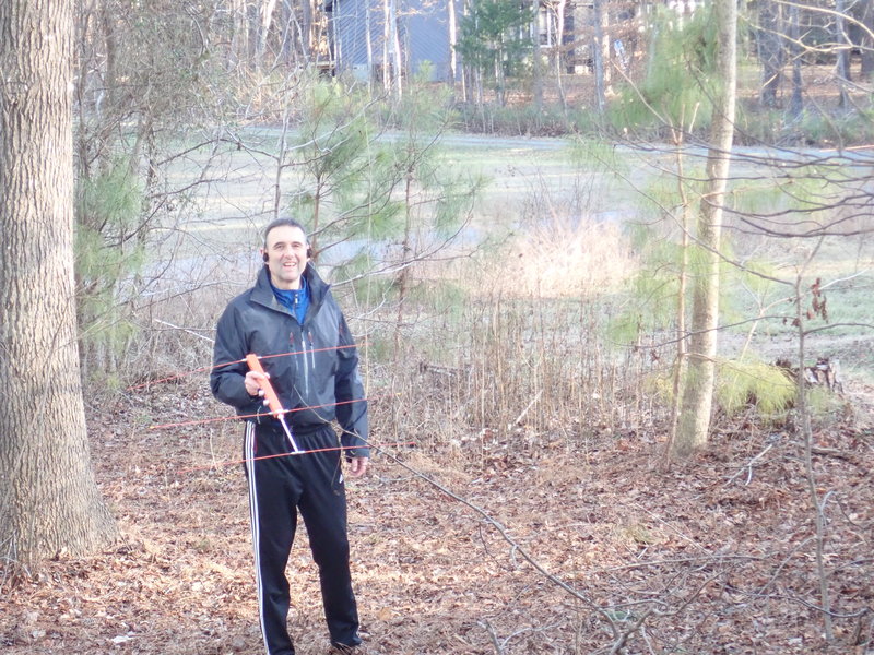
Fig. 4. Patrick testing one of the PJ-2D receivers with the new transmitter. I just got back from walking up the road. "Kelly, it's going to work!" It wasn't enough for us to be able to hear the signal from several hundred meters away using our better receivers. We also had to be able to hear it with the PJ-2D the students would be using. We could hear it from the furthest point I walked to, about 350 m away. It's not far, but it's far enough for our first school events.
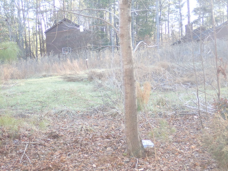
Fig. 5. ARDF 2 m transmitter in the field. The antenna can be seen to at top of the image slightly to the left of center. It's the short white tube with rods sticking out of it. Two of the rods are in profile. The other two are foreshortened and quite a bit harder to see. Coming down from the antenna is the feed line, a 3 m length of RG58 coax (black). On the feed line, the RF choke beads can be seen; they have a piece of white electrical tape on therm. The transmitter and battery pack are in a plastic box just to the right of the foot of the tree. We adapted antenna design from one put on the web by Jay Hennigan. As an aside, Jay will be helping put on the US ARDF championships in Truckee CA this summer.
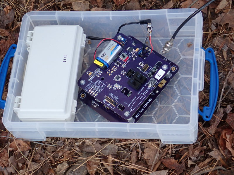
Fig. 6. Close-up of the transmitter and its battery pack in the field. The battery pack is on left. On the right, we can see mostly the controller PCB. It's all still loose. But putting it in a case can't mess things up. Or can it?
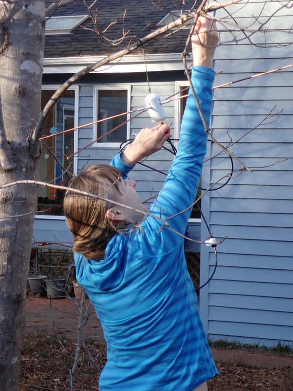
Fig. 7. Kelly taking down the antenna. Here is a closer look at the antenna. The feed line (black) enters the white PVC tube from the bottom. Inside, it connect directly to two of the rods. Also connected to these two rods is a phasing loop that sends part of the signal to the other two rods. The radiation pattern ends being pretty much a circle in the horizontal plane.