63 — PRS ARDF 80m version 2 transmitters are built.
2016-03-13. By Patrick.
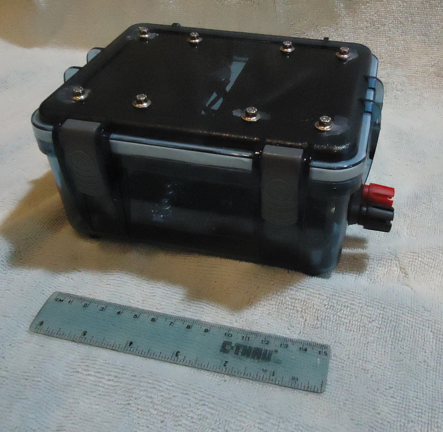
Fig. 1. PRS ARDF 80m transmitter, version 2.
This last year has seen success after success coming faster together. It's been incredible. It really spead up when I figured out a truly working powerchain from the Si5351 to the antenna. A few weeks ago (see blog post 59), I finally got transmitters built that we were going to use for events. Those were transmitters number 1, 2, and 3. They were big and clunky but fully functional and field ready.
This Sunday was another big step. Transmitters 3, 5, 6 were completed (Fig. 1 and 2, Fig. 3 for the bottom). For the first time, the transmitters have their final outer form. Their longest dimension is about 18 cm when the antenna wire binding posts are included. They are much smaller than the first three and will easily fit in a backpack.
A few notes about version 2. I knew this would be the final shape of the transmitters and was tempted to order enough PCBs to finish all of them. The plans are two build 15. Twelve will be enough to run a sprint event (5 slow foxes + 5 fast foxes + 1 spectator control + 1 homing beacon). Then, 3 extra in case of breakdowns makes 15. OSH Park requires at least 3 boards to be ordered. That's a nice number. As I mentioned in an earlier blog, building 3 at a time has advantages when it comes to testing. If all three fail, there is a design error. If one fails, there is a building error. And there are _always_ design errors. Always. No matter how sure you are, there is always some smalling thing that should be different. Well, not in this case. This time there was a _major_ problem on top of the usual small ones. One of the kicad module pin configurations didn't match the parts I was using. Arghhhh! >: ( I'm not going to explain how I made that mistake. There are already countless ways to make dumb mistakes and humans are quite proficient at finding new ways. So, next time you think you should skip ahead for a tiny gain in time, don't do it. Trust in your human qualities, build just a few, and test. Anyway, all came OK in the end with an ugly twisting of pins. You may notice where this happened in looking carefully at Fig. 4. The TO220 at the top edge of the PCB (just to the right of "2016 ip...") is at a 90 degree angle from the silkscreen outline. It's the LM317, voltage regulator. The same thing can be seen for another TO220 in the foreground (at the edge of the board and slightly to the right of the shrouded 2x3 ISP header). That one is the IRF610, power amplifier.
Version 3 is already mostly designed and includes more than 10 small changes. And one major one of course. As usual, we're already eagerly looking forward to having them built. But suddenly, with the three version 1 transmitters and these three version 2 transmitters, we're looking forward to something new. With 6 transmitters, we can run a full classic event. Yippieeeee! Can't wait to get out in the woods.
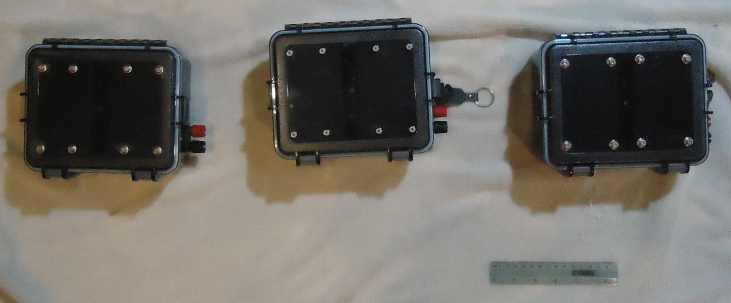
Fig. 2. The three new transmitters; transmitters 4, 5, and 6.
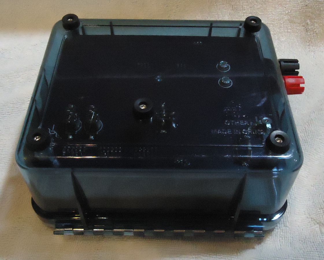
Fig. 3. Bottom view. Five feet.
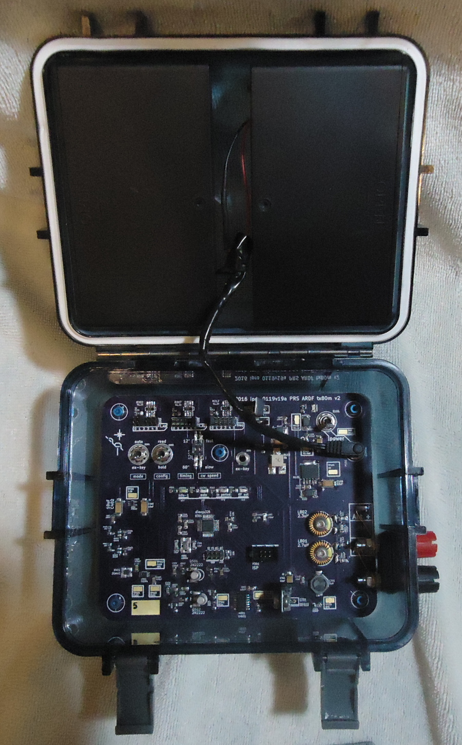
Fig. 4. Inside view. The battery cases fit perfectly in the top. This is transmitter number 5; there is a small 5 on a pad at the lower left of the PCB.