61 — Tests of ARDF 80 m transmitters and antenna matching
2016-02-28. By Patrick.
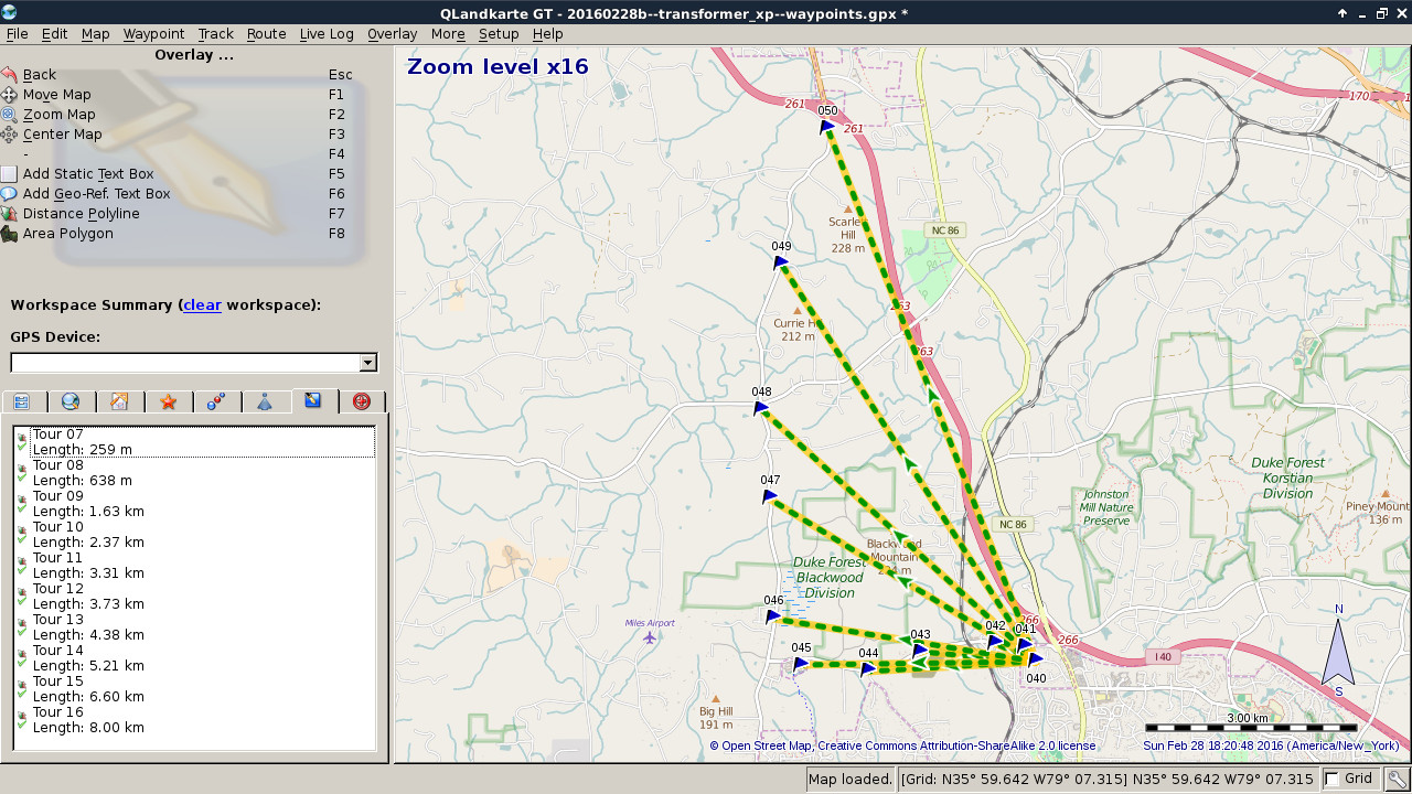
Fig. 1. Using QLandkarteGT to measure distances from the antenna to the listening locations. This is the map used for the second experiment. I used QLandkarte's polyline feature to measure the distances.
In the last two weeks we did a couple interesting experiments. We finished building version 1 of our 80 m transmitters. Naturally we wanted to know how they performed when compared to the lower power transmitters we were using the year before. Also, we came across so good information about an antenna matching transformer used for 80 m ARDF and I built that. So how large of an area could cover now?
The simple testing system we've been using for a while now is to first set up the transmitter in the front yard (Fig. 2 has Kelly at the transmitter). For the two experiments described here, I used a 6 m vertical and four 3 m ground radials. Then we drive away and stop at intervals to listen for the transmitter (Fig. 3, Patrick listening). Usually, as on this last Sunday, Kelly drives and I hop out of the car to listen when she stops. I use a receiver with a gain knob with settings numbered 0 to about 7. When I listen, I first turn the gain up until I can hear the signal clearly and then turn it back down until I reach the lowest at which I can still hear the signal clearly. That's the datum I record, the minimum gain at some distance. At each listening stop, we either note the location or take a GPS waypoint. When we get home, I bring up a map of the area in QLandkarteGT (Fig. 1) and measure the distance to each listening location.
The first experiment (Fig. 6) was the comparison of our old transmitters (TX-1) with our new ones (TX-2). The old ones have a fixed power output of about 30 mW (I need to check this). The new ones have a controllable power output which I had set to about 1 W and which could reach over 5 W. As you can see, I could hear TX-1 out to about 1000 m. That has worked well for around the school or for quick practices. And these transmitters are nice and small. The TX-2 we could still hear beyond 3 km. Seeing this... Well it was Happy Times. We put a lot of work into designing and building these and the power output was more than marginal.
The second experiment was the test of a transformer. At the last ARDF meet I had attended (Colorado, 2015-08), Brian DeYoung and Matthew Robbins had told me that a transformer would likely make a big difference. I search around the web for information, and before I had a chance to ask for some more help, I found a write-up on the www.homingin.com web site. It mentioned a transformer that Dale Hunt (WB6BYU) had used for the 1999 IARU Region 2 ARDF Champioships in Portland. The transformer consisted of an Amidon T130-2 toroid with 5 turns on the primary to hook up to the transmitter and 55 turns on the secondary to hook up to the antenna and radials. I would such a toroid (Fig. 4) and put it together in a small enclosure (Fig. 5).
On to the actual experiment. This last Sunday, we re-tested TX-2 with the same antenna configuration and with the addition of the transformer (Fig. 7). As you can see, we could hear TX-2 just beyond 3 km when there was no transformer; same as in the last experiment. It sure is nice when experiments done on different days give the same results. Then, we added the transformer... Wow! We could hear it almost out to 7 km with just 1 W of output. Well, that's it. We're done. There really isn't an ARDF event we can't run. Time to build the rest of the 80 m transmitters. And then, on to 2 m!
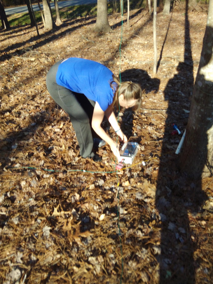
Fig. 2. Kelly turning off the transmitter at the end of the second experiment.
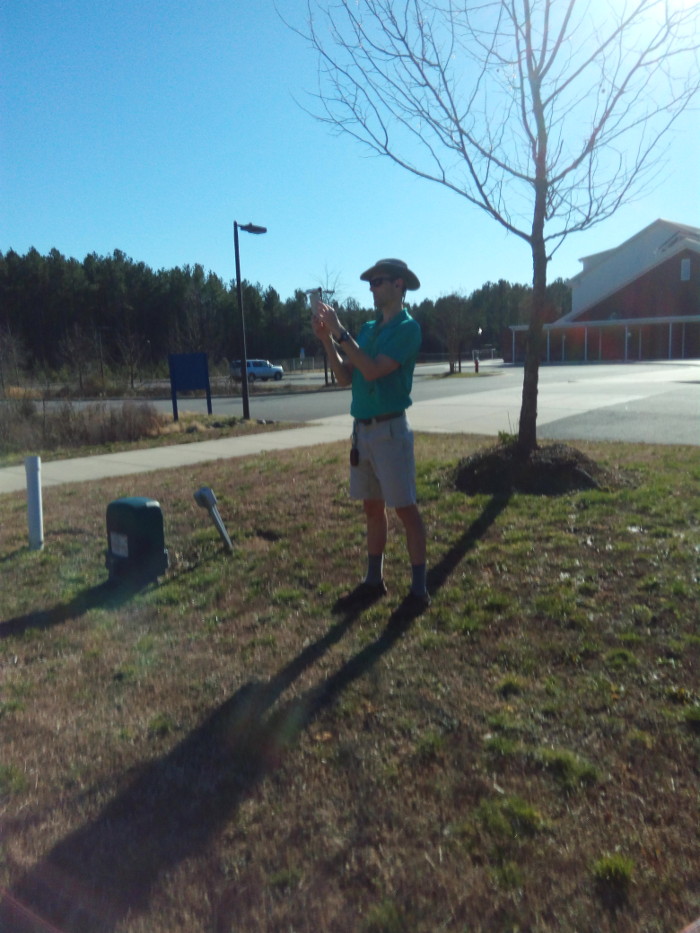
Fig. 3. Patrick listening for the signal by the school (waypoint 45 in Fig. 1).
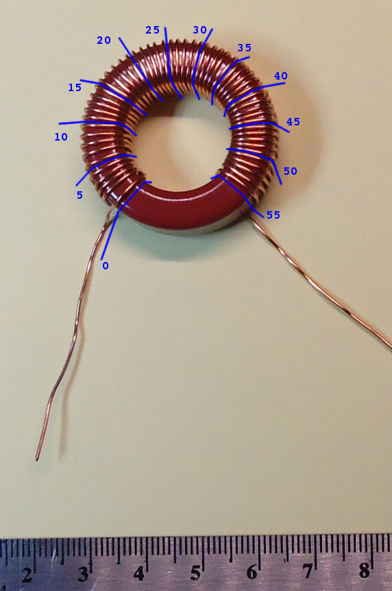
Fig. 4. Using image overlays to check the turn count on a toroid. This is a technique I use with any toroid that takes more than a few windings. I would approximately the right number of turns, I take a picture of the completed winding, and I check it on a computer where I can blow up the image and take my time.
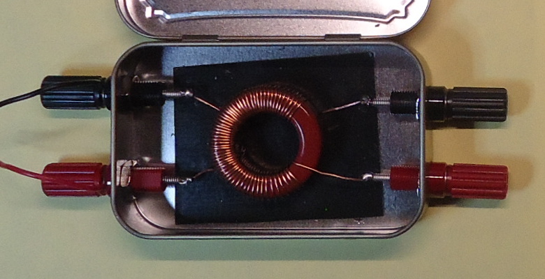
Fig. 5. Transform completed.
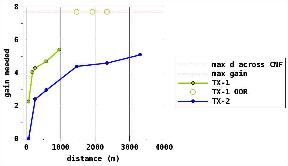
Fig. 6. First experiment - small low power transmitter (TX-1) and new transmitter (TX-2). The open circles up high (TX-1 OOR) denote location at which we listened but where we were out or range.
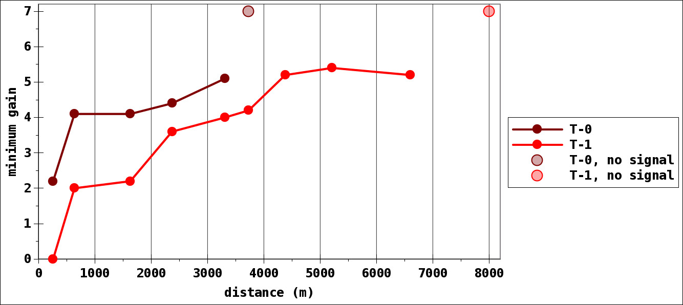
Fig. 7. Second experiment - new transmitter tested without and with the antenna matching transformer. TX-2 tested without the transformer (T-0) and with it (T-1).