59 — ARDF 80 m transmitter single board, build finished
2016-02-14. By Patrick.
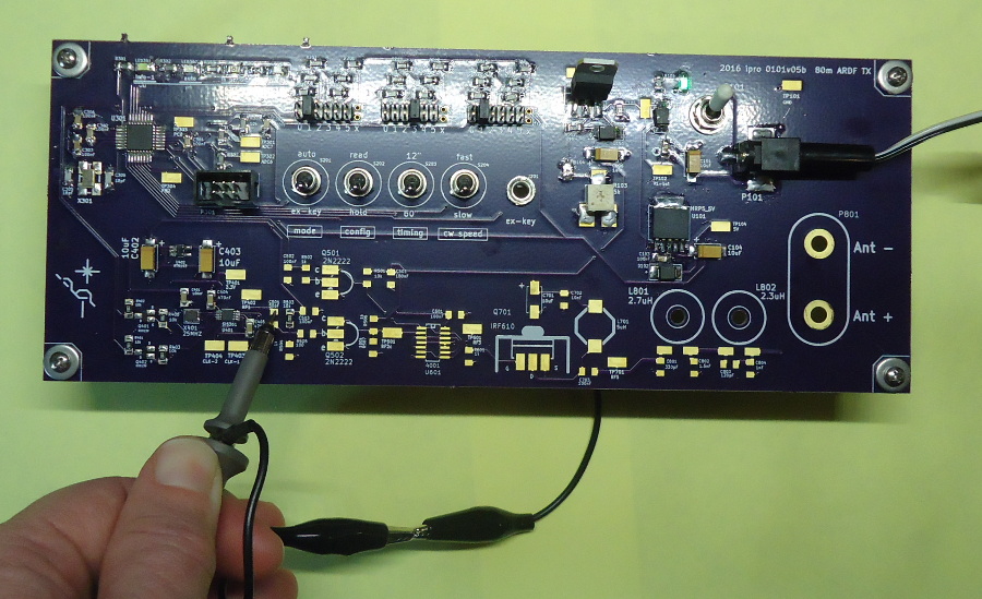
Fig. 1. Transmitter with all soldered up to the border between the oscillator module and the pre-driver module. I'm putting the probe on the oscillator output test pad.
Finally the first three transmitters are built. I have a long list of changes to make before I send the gerbers to OSH Park for version 2. But, these are the first set of transmitters that will be used for events. We are getting very excited.
I soldered all three PCBs at the same time. Stopping after each module to take measurements to document the build process and to make sure that all was working correctly. It took much longer to get the first transmitter built but it took much less time overall. And it was great always having three PCBs to test. Something unexpected in only one of them meant a soldering error. Something unexpected in all three meant a design error. I'll definitely do it the same way when building version 2.
Figures 1 and 2 show a partially built PCB being tested and the resulting oscilloscope trace. All the components soldered are for the modules prior to the pre-driver. This is a major point in the built for two reasons. First, it's the first time that RF can be measured. Second, all the really tiny and tough components are soldered and so there is a much lower chance of soldering problems after this point.
About a week and a half later the transmitters were totally built (Fig. 4) and we went to the school to test them for the first time (Fig. 5). It took about two weeks to completely build them. One week for all the soldering and one for putting together the enclosures with the battery packs.
Two of the transmitters are just placed in plastic boxes with some padding. Someday we may get real enclosures for them, but maybe not. These version 1 transmitters are a fair bit larger than the plans for version 2 transmitters. So we may use them as homing beacons, spectator beacons, and spares. These don't have to be carried as far into the woods.
So there it is. We finally have three transmitters built. They can put out several watts of power and can be used for any type of event. There is still plenty of designing, building, and documenting to do. But, suddenly, my entire mindset has shifted and I'm thinking much more about running events.
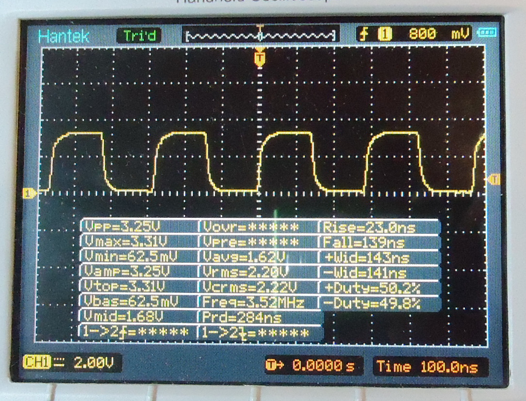
Fig. 2. Trace from the oscillator output.
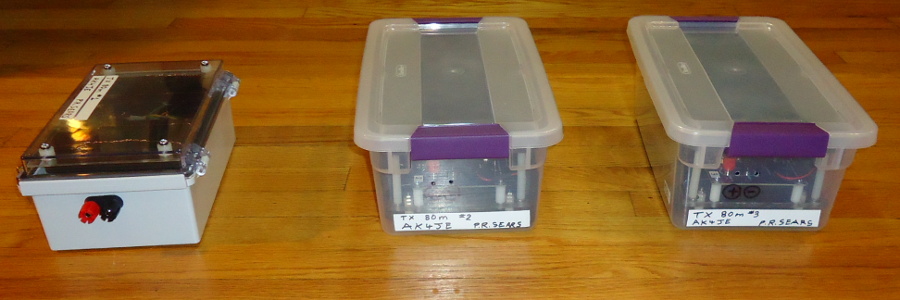
Fig. 3. 2016-02-14, Sunday, around 11:00. All three transmitters are built.
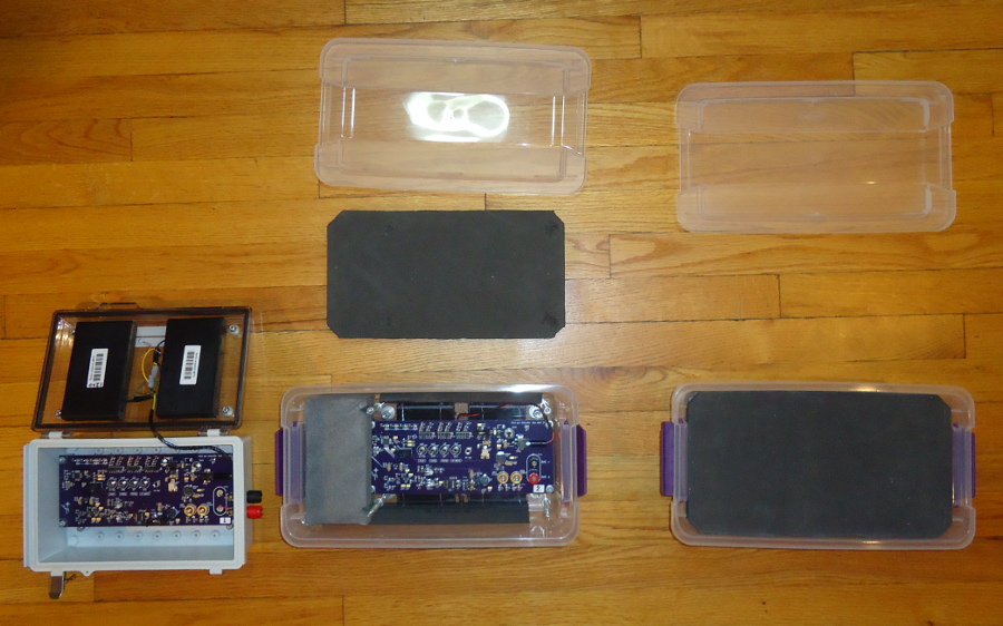
Fig. 4. Transmitters opened up to show the insides. TX #1 at left has a nice enclosure. TX #2 and #3 are placed in shoe-box sized Sterilite boxes with foam padding. TX #2 in the center has the top padding removed and shows PCB.
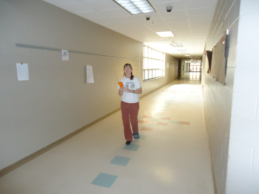
Fig. 5. After the transmitters were built, we had lunch and then went over to the school to test the transtmitter out for their first planned used: Enrichment Club. Here Kelly is walking down one of the school hallways with a receiver.