51 — MSOP-10! Is there no limit to how small we'll go?
2015-12-20. By Patrick.
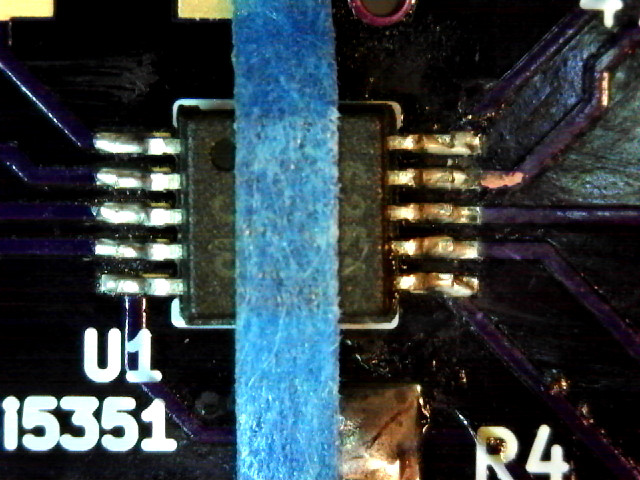
Fig. 1. Picture taken with USB microscope of the MSOP-10 Si5351 held down on the board with blue tape. On the right side, some damage to the board covering shows where I had some problem getting rid of shorts.
In the last blog entry, I wrote about our success in getting the 80 m transmitter power up to acceptable levels. That was truly a great moment. But there was a bit of a worry still. The Si5351 only comes in an MSOP-10 package.
Let's see what this means. I like to design projects without through-hole connections. That's easy to do even with through-hole parts. Just bend them at a 90 degree angle and solder them on to a pad. Generally, the pins on these parts have a pitch of 2.54 mm. So when a long DIP needs to be soldered down, we have to be careful. But really, a bit of experience with this and it's a piece of cake. But going smaller?
The SOIC was next for me. It had a pitch of 1.27 mm, half that of the DIP. That seemed pretty hairy at the time. But again, time passes, experience is gained, and it becomes routine.
The next madness was the TQFP. The ATmega328 that is so popular comes in a 32-lead TQFP that is only 7 mm x 7 mm. Wow, that could really reduce the size of boards. But the pitch is 800 um! Taking this on was truly madness as we didn't have our hand forced. After many problems, I realized that I needed to be more careful with the heat as I soldered. The problems I was having were not shorts or cold solder joints. I was destroying the controllers. But not completely, just enough to make me think that there was a bad connection somewhere.
But the madness was not over. We wanted to use the Si5351 for the 80 m transmitter. There were a number of reasons for this but mostly it comes down to knowledge momentum. When you see many other people using a component and there are plenty of examples on the web, and then you try it out and get familiar with it, pretty soon everything gets easier using that particular component. I would have been perfectly happy using other people's breakout boards like the one Adafruit makes. In that's what I used starting out with the Si5351. But we would have to build more than twelve transmitters if we wanted spares. It would sure be nice to have the entire transmitter on a single board. The problem was that the largest Si5351 was the MSOP-10, a 10-pin package with two rows of pins and a pitch of 500 um. I'm done putting exclamation points at the end of sentences that mention an even smaller pitch. It's just crazy. Or to adapt comment from Sartre, It's not a 500 um pitch that's insane, it's not me that's insane, it's me trying to solder a 500 um pitch part that's insane.
We did have the OSH Park boards made and ordered the Si5351s. I re-read all the tutorials I had found on soldering small SMT parts. And gave it a go. Fig. 1 shows the Si5351 just after I got it soldered. It wasn't easy and I'm still not sure that the best method is. Others will be better at explaining how to do it. But at least, know that I have a bit of a shaky hand and I got it to work. So take heart. I'm not sure it's necessary, but I personally found much comfort in looking at USB microscope image as I was working.
When I was done, I brought it over to the transmitter. I disconnected the Adafruit Si5351 breakout and connected the new OSH Park board in its place. And of course, it didn't work. It never works the first time. But the problem was solved pretty quickly. The crystal's datasheet had a small note that the chamfer marking pin 1 was sometimes on pin 4 (see Fig. 4). I hadn't noticed it but the chamfer on the chip I had seemed strange. I unsoldered the crystal, replaced it placing the chamfer on position 4 on the board. I hooked it back into the transmitter and measured full power at the dummy load. It worked. Happy day.
I haven't measured the output directly at the Si5351 yet. The probes were already setup for doing the power measurements and that's why Fig. 3 shows the voltage at the dummy load. Some time I'll check out the output directly at the Si5351. But for now, the transmitter works with our new Si5351 board. Happy, happy day.
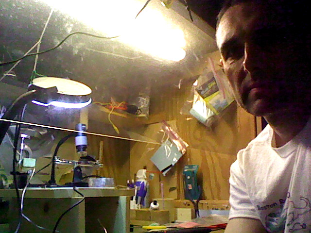
Fig. 2. The soldering setup. There is an acrylic shield that extends about half way down the front of the box where the working is going on. The Si5351 breakout board is held horizontally in some clips and so can't really be seen. The clips are on a black stand, itself one a wooden platform in the box. The USB microscope can be seen sitting on the wooden platform. There is plenty of light in there. The laptop that I used as I soldered is on a stand just to my left and its integrated webcam is what took this picture. The entire setup is in the garage.

Fig. 3. Initial test of the Si5351 breakout board. The top-left panel is a wide view of the setup. What a mess! It's the result of the tornado of work trying to get the transmitter power up. The bottom left panel is a view from the side. The nice OSH Park board can be clearly seen here, hanging in the air by wires. The bottom right panel is a view from the front. The OSH Park is at left and the pre-driver module is at right, both hanging in the air. Below them, the small Adafruit board is still bolted on to the acrylic but not electrically connected. The top right panel show the sine wave at the dummy load. Happy day!
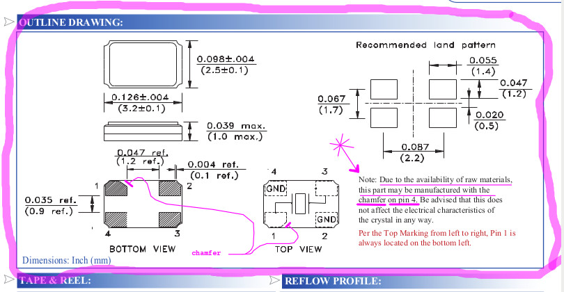
Fig. 4. Snapshot of notes I had taken on the Si5351 PDF (using Xournal). The pink marks are mine. I used the measurements here to make the pad layout on our OSH Park board. But the crystal we purchased had a chamfer with a different shape. Only after soldering on did I get suspicous and look back at the datasheet. That's when I noticed the note about the chamfer possibly being on pin 4.