49 — TX-80, we have power!
2015-12-06. By Patrick.
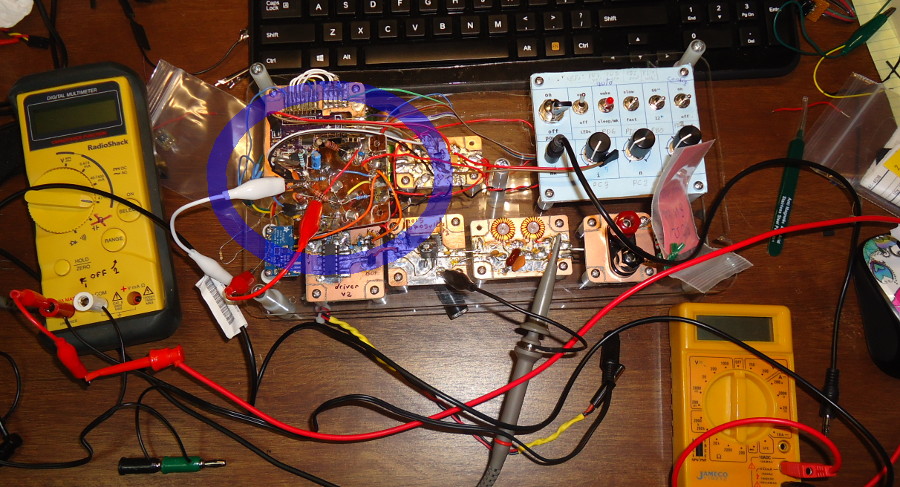
Fig. 1. After an evening of tweaking and testing, the wiring gets pretty messy. The new pre-driver module that finally got it working is hanging in mid-air in the blue ellipse.
After months of trying different configurations, finally, we have power!
I've been trying to get power out of our 80m ARDF transmitter using the Si5351 as the oscillator. And failing. And failing. And...
Anyway. After much studying and trying different ways of doing it, I finally came to the conclusion that I could not get the 3.3 V put out by the Si5351 to drive the NOR gate driver and then the IRF610 power amplifier. Probably, it can be done. But I don't know how to do it. I could drive the NOR gates when the voltage supply was low but then I couldn't drive the IRF610. Or I could drive the IRF610 with the NOR gates using a higher supply voltage (using a function generator instead of the Si5351). But putting it all together never worked.
I decided to design "pre-driver" to place between the Si5351 and the NOR gate. I don't know how to design such a circuit but I studied a lot in the last few months and I tested bunch of circuits. I decided to use the 2N2222. I had some around and I had used it in an earlier transmitter using one of the colorburst crystals. I designed the input biasing part from calculations of the voltage swings I suspected would work. Then, I just built an ugly-construction board and hoped for the best.
But really, after this many months of failures, I didn't expect the ordeal to be over. The great thing about ugly construction is that it's so easy to tweak and this was going to require months of full alterations. So, onward with the first step. I hooked up the oscilloscope probes to a couple places along the RF power chain. I hooked up the bench-top power supply set to a low voltage. Flipped on the switch. Waited a bit... OK, no smoke. IRF610 heat sink is staying cool. Slowly started increasing the voltage on the power supply. Starting to get some signal at the IRF610 output. Upping the voltage some more. The signal at the IRF610 output is really coming up. It's very "spiky" looking. Switch the probe to the output of the filter where a 50 ohm dummy load is connected. OK, the signal there is low but it's definitely getting through and looks like a nice sine wave. More voltage in, more, still no smoke, more. Wow 40 V peak-to-peak! That's over 4 W out. The heat sink on the IRF610 is warming up but it's not getting burning hot. We did it!
And this is not one of those "small successes" that I have written about. This is the game changer. I'm sure that the design could be greatly improved by someone trained in electronics. But this is not a design I grabbed off the internet and soldered together. I took parts from all different people's work and figured out how to make it all work together. It feels really good.
So we're finally moving on. We've started designing the full board. I'm dividing the project into modules and sending these boards to be made by OSH Park. When we have these all back, tested, and tweaked just the way we want, we'll have full boards made. And then, onward to 2 m!
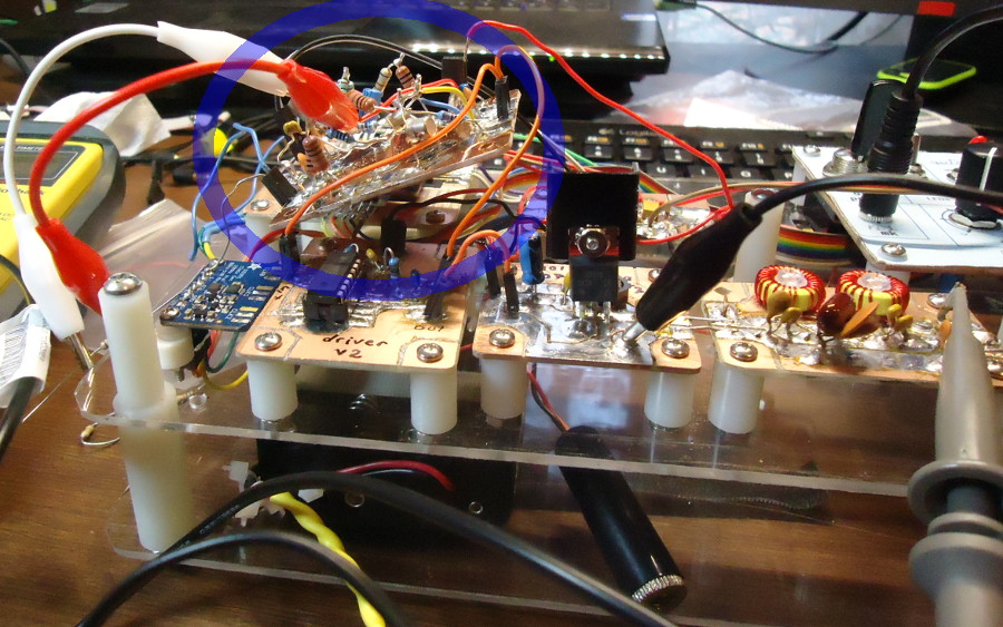
Fig. 2. Side view. Yup, that pre-driver is hanging in mid-air with just the wires holding it. "It's working! Don't touch anything! Just give me two minutes. I need to make sure I wrote down the configuration correctly."