47 — Home made vias.
2015-11-22. By Patrick.
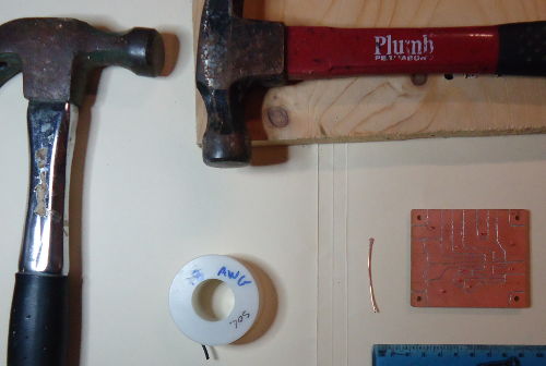
Fig. 1. Tools and materials. Two hammers, one is used as a hammer and the other as an anvil. A spool of solid wire, 18 AWG to make short pieces with a flattened end (one shown at right of spool). We'll also need some pliers and wire snips. In the right foreground, there is the board with via wires already inserted and cut, ready for soldering.
This is a short entry describing the solution to a problem I have had for many years--how to make home-made vias.
Let's say you want to make a PCB prototype. You could use ugly construction or a dev board. Some traces will have to cross and so you'll have to solder on small jumpers. But you decide you want to cut your own copper and you also decide you would rather cut a two-sided board and make vias.
When I get to this point, I usually grown and change my plans. Instead, I usually decide to solder on jumpers or go full-ugly after all. If you just want to know a good way to make home made vias, skip the next paragraph. But if you're thinking "I'll just drill some holes and pull a wire through", see what comes next...
When I have tried to make vias at home, I have been plagued by three problems. First, combinations of wire size and drill bit size that result in a tight fit are hard to find. And when a perfect combination is found, the drill takes out a tiny bit more material on the next hole and the fit is too loose. And on the next hole, the drill takes out a bit less and it's to tight. Anger is building but I'm determined. The loose wires keep falling out as I try to solder them down on one side but we finally get them all done. Next I start to solder on the other side. The wire is a very good heat conductor. As I solder the second side, the wires fall through again. I start bending wire on both sides of the board to get them to stay in place. Here comes the second problem--bent wire changes shape as it is heated. The bent wires appear to be nice and snug until heat is applied and all loosens up again. At this point, I have spent more time fiddling with the stupid wires than I have for the rest of the project. Anger has built up to such a point that there is as much smoke coming out my ears as there is smoke coming off the soldering iron. Problem three: Finally I'm done. It took a while but I guess it was worth it. I start checking for connections and shorts. Usually, this is just a precaution before I place components. Some of the bent wires were in tight spots were I had only expected to deal with a wire running straight through the board. And sure enough, a couple of those bent wires shorted to the adjacent track. Back to the de-soldering, bending, re-soldering. Oh, and I forgot, there is a fourth problem: we haven't gotten to soldering on the components yet. And the via wires will come loose again.
OK, the problem is finding wires that will hold in imperfect holes, stay jammed when heated, and can be kept straight and perpendicular to the board surface so that they use up minimal space. One solution that worked for me on the last two boards is to take each short piece of wire and repeatedly hammer one end until it is flat and wide. I then insert the rounded end through the via hole and pull through with pliers until the flattened end has jammed real tight into the hole. I then cut the protruding ends and solder. No problem, fast, and super simple. Good for the Wa. The holes need to be large enough to easily fit the round wire through but no larger. Solid 18 AWG wire in holes drilled with a press and a 13/64" bit worked well. After soldering, I cut the wires further down. I used this system for two versions of the oscillator-driver module for the ARDF 80m transmitter prototype.
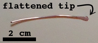
Fig. 2. Close-up of wire peice to pull through via hole.
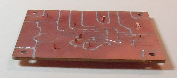
Fig. 3. Side view of board showing top view with via wires pulled through and cut. On this side, all the flattened ends protrude. This is the side into which I inserted the wires.
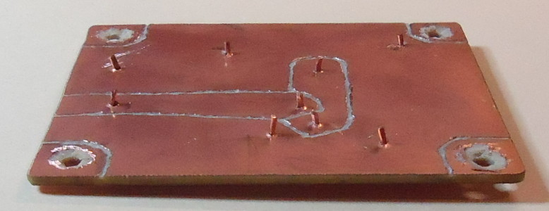
Fig. 4. Side view showing the bottom. This is the side from which I pulled the wires through with pliers.
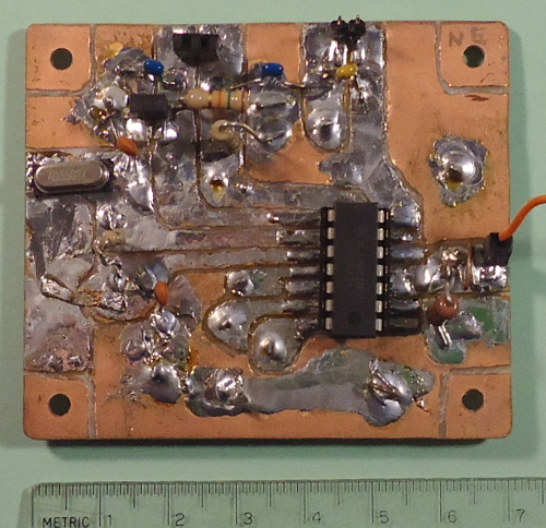
Fig. 5. Completed oscillator-driver module for the 80m transmitter prototype.
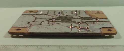
Fig. 6. Side view of another version of the module. This one doesn't have any of the components on it yet. The via wires are cut down to their final height, the copper is tined on surfaces where components will be added, and a ground test point has been added (small loop in foreground on right).