45 — Transfer your circuit drawing onto copper.
2015-11-08. By Patrick.
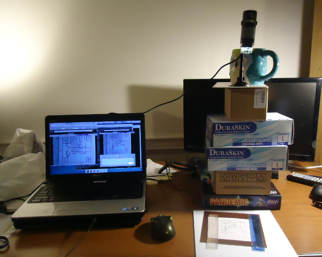
Fig. 1. Picture of the setup. The laptop is at left and is running both pqiv and kamoso (webcam software) on the right and kmag on the left. The USB microscope is perched high on top of boxes at the upper right. The diagram is held flat onto the copper with two rulers in the foreground on the right.
I just discovered a new way to transfer a circuit diagram to copper. And it's tres cool. I'm not talking about the nice circuit diagrams created by CAD software. I'm talking about stuff in between ugly construction and those nice circuits. The type of circuit for which you'll cut some copper with a dremmel in twenty minutes. You might have 14-pin DIP to put on and want to get to get that spacing done carefully but the rest doesn't matter too much.
So you have a diagram on 10 squares-per-inch graph paper so that you could get the DIP spacing exact. You also added screw holes that have to be precise to match holes in an enclosure. It's time to transfer the drawing to copper so that it can be cut, drilled, and etched. If this was just a transfer from on piece of paper to another, I would tape both pieces on top of each other on a window so I could see the drawing through the top paper. But copper board is opaque.
Recently we purchased a cheap USB microscope to help soldering the MSOP-10 Si5351. It was playing around with the microscope that I had this great idea. Get the circuit diagram onto a computer image. Set the background to transparent. Somehow display it allowing the desktop and other windows to show through the transparent parts of the image. Then bring up the USB microscope looking at a blank piece of coper. And trace the diagram onto the coper while looking at your pen on the computer screen with the diagram overlaying the live USB microscope window.
Of course it's not that simple. All image displaying programs I had seen up to now showed transparent parts of images with a checkered gray pattern. But there are obviously plenty of screen savers that have transparent effects. So there should already be some program out there that could handle this. There were other potential problems. Would the microscope video latency be too slow? Would the microscope be able to focus at the distance needed? Would getting the scale right be a pain? Because enough problems would make it easier to just reproduce the drawing carefully with a ruler. Time consuming, boring, error prone, but it's what I had always done in the past.
Now we're moving into the system-specific realm.
I'm using Debian 8 Xfce.
Some of what I describe will work on other systems.
Some will need altering.
After some searching, trial, and error; I solved the first problem.
A program call pqiv and available via apt-get can bring up an image with its transparent parts truly transparent.
I placed the following command in a bash script with a quick name to type
pqiv -c --disable-scaling "im03.png"
The image was named im03.png.
I had drawn the diagram in black on graph paper with a blue grid, scanned it with xsane, and used gimp to turn white to transparent.
The pqiv -c option is the one that causes the background to be truly transparent.
But it's not that simple.
For the -c option to work, the display manager must have "compositing" turned on.
I don't know anything about compositing but it was not on by default.
To turn it on in xfce, you have to go to the "settings editor", find the xfwm4 channel and then the use_compositing property.
There you can change its value from false to true.
Be careful if you have never done this before.
If you're not careful, you may do like me and think that hitting the Reset button will put stuff back to the way they were before you fooled around with the settings.
Actually, that deleted the "use_compositing" property.
I had quite a time searching on the internet to figure out how to get it back.
Here is a simpler searchable solution.
Create a script with the following two lines:
xfconf-query -c xfwm4 -p /general/use_compositing -T
xfconf-query -c xfwm4 -p /general/use_compositing -v
The first line toggles compositing (-T),
the second displays (-v, verbose) the value so that you can see what it went to.
I don't know much about compositing and this is the only time I have needed to mess with it.
From the reading web posts, it looks like it may need to be turned off for some games to work.
So having a quick toggle may be useful for some people.
Finally the tracing. I couldn't find a good way to zoom the image with software. So I raised the microscope until the diagram displayed by pqiv matched exactly the one displayed by the webcam software. I had to raise the microscope really high. More than 30 cm maybe. I also tried a regular webcam but I couldn't get it to focus when the scale was right. Looking around for a way to zoom the image on the screen, I tried a screen magnifier (kmag). It didn't have a smooth zoom, but it did magnify the part of the screen where I was working.
So far, I traced one board. It's an oscillator and driver for our on-going experiments with the 80 m ARDF transmitter. I had already built one but I wanted one that would fit better in the enclosure. It came out well. The traces are not as neat as they were when I replicated them using a ruler. I haven't cut the copper yet but the diagram definitely looks good enough. And even with the microscope jury-rigged high up in a hurry, it was still way faster than replicating all with only a ruler.
I also tried tracing from a diagram created directly on the computer. But for me, tracing the original drawing on graph paper went faster.
I bet this type of system has been implemented for other purposes. But I haven't come across it before. And for transferring circuits to copper, I'll definitely use it again. Tres cool.
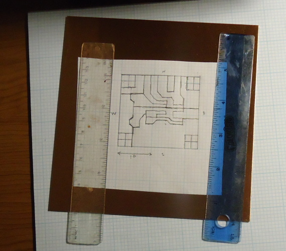
Fig. 2. Diagram under the microscope. I'm imaging it to adjust the scaling and to ensure there is no distortion. When the kamoso image matches the pqiv image, I'll remove the paper and start tracing on the coper with a sharpie.
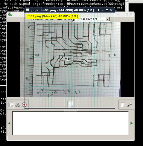
Fig. 3. Screenshot of piqv and kamoso running together with the diagrams mis-aligned to show the the pqiv diagram on top and the kamoso diagram showing through the pqiv transparent background.

Fig. 4. Screen shot of full desktop with the two diagrams perfectly scaled and aligned. On the right, pqiv and kamoso show only one diagram since they are lying exactly on top of each other. On the left, kmag shows a magnified view of the right portion of the desktop.
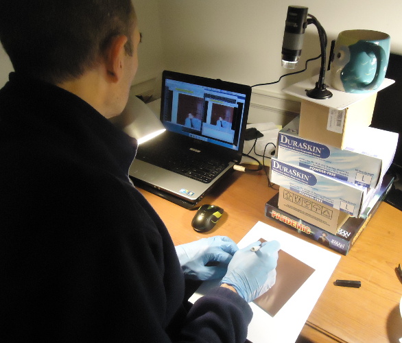
Fig. 5. I have removed the diagram from the copper and am tracing on it while looking at the laptop screen.
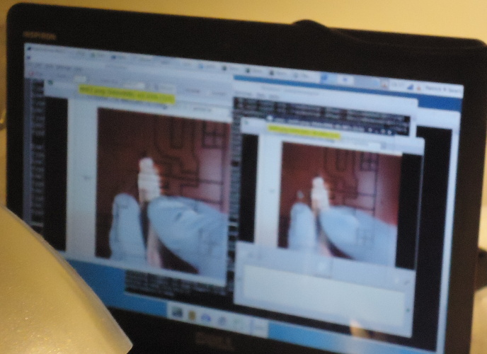
Fig. 6. What I'm looking at as I trace. The picture is a bit blurry but you get the idea. I'm looking at my pen on copper in kamoso and making it follow the diagram superimposed by pqiv.
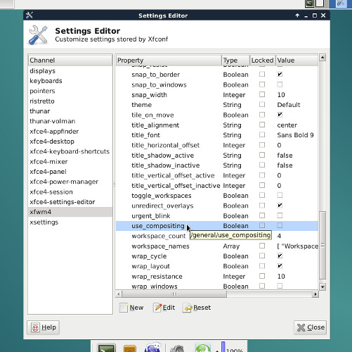
Fig. 7. Where to find "use_compositing" in the xfce settings editor.