39 — Starting to build the prototype for our new 80 m transmitters.
2015-09-27. By Patrick.
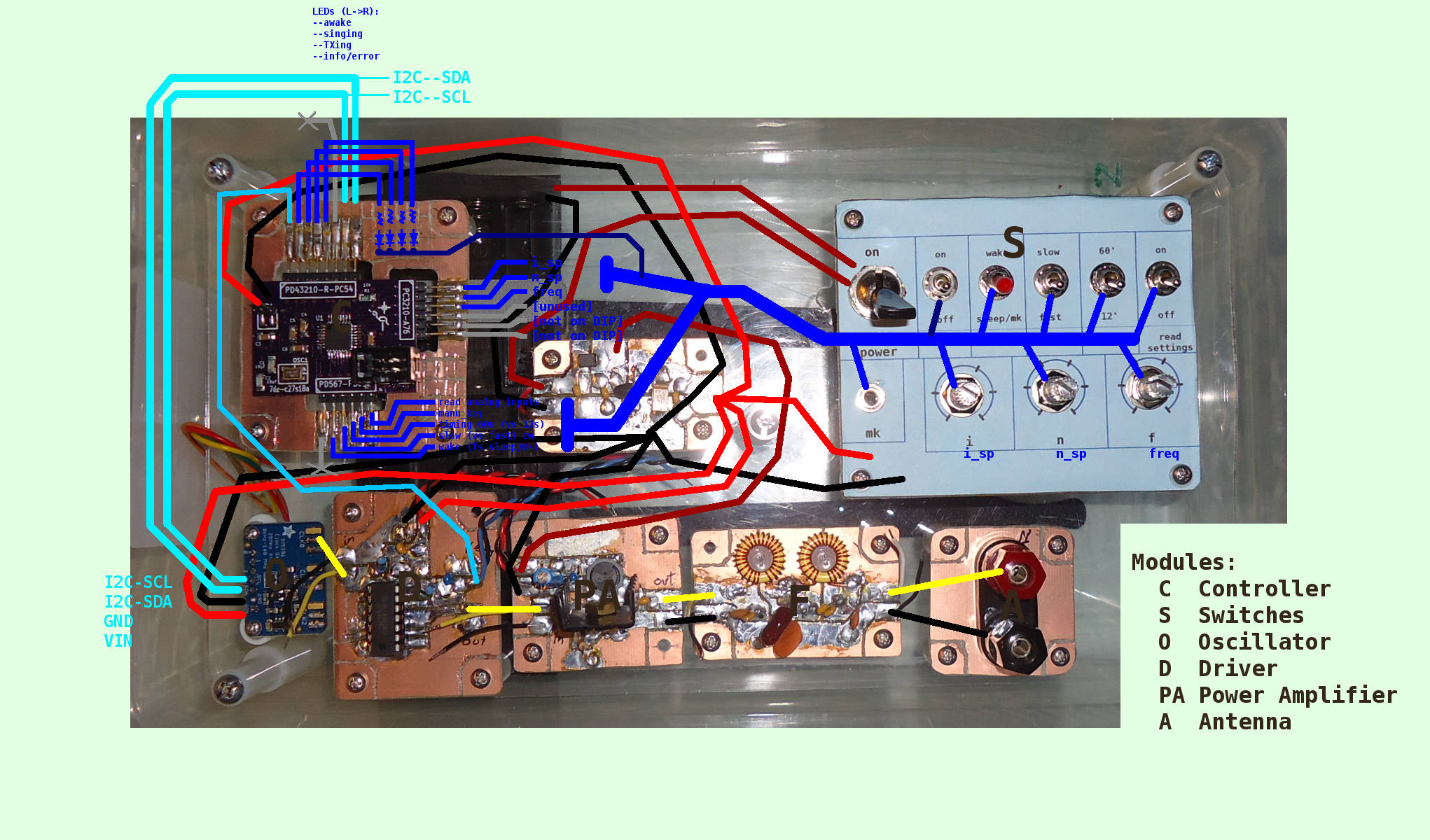
Fig. 1. Top down picture of the transmitter in the plastic box. All the connections between the different modules are marked with colored lines. Black is the ground. Red denotes the voltage supply lines. Blue lines are for switches and LEDs. Light blue lines are for the ATmega to communicate with the Si5352 (I2C) and driver module. Yellow lines are for the RF.
On Sep-17, I Started building the new case for the ugly-construction (UgC) version of our new 80 m transmitter. The new plan was to build the UgC version in a shoe-box sized plastic box instead of a small metal box like the ones we used for our two low-power 80 m transmitters. These last two were based on Jerry Boyd's Microfox transmitter but used an ATmega328 as the controller. Also part of new plan is to build the UgC in larger modules that are easy to swap and alter. But the major changes are in the design of the electronics. This new version will be based very loosely on a transmitter designed by Rik Strobbe but will use an Si5351 as the oscillator. The new RF power chain should provide a fair bit more power than the Microfox design can accommodate. And the Si5351 will make several frequencies available.
When all is working with the UgC version, we will adapt the design to fit on a single smaller board and send the gerbers to OSH Park to have the PCB made. Finally, when the first few OSH Park boards are built and tested, the UgC version can be dismantled and the modules re-used in other projects.
This last Saturday (Sep-26), I finished building the main hardware for UgC version. It doesn't have much of the software written yet and so all it's doing is blinking LEDs. But it looks really good. It has all switches and connections built onto acrylic boards that fit completely in the plastic box. The plastic box has tabs for closing and is easy to open and close and the transmitter can be pulled out of the box and put back in easily. Having all the switches and connections inside the box saved much time since I didn't have to fiddle with getting an enclosure drilled and running wires between the board and the enclosure. Any time I want to make some alterations, I just pull the entire thing out of the box and set it on the workbench. The design of the UgC version also makes it easy to test in the field. Since there are no switches or other parts that hang outside the box, it slides easily in and out of my backpack. And it will be easy to keep the rain out of the inside since there are no holes in the box top or sides.
The next steps are to adapt the software written for our low-power transmitters to control this new one. A big change will be the addition of I2C code to communicate with the Si5351 and code to control the Si5351. Then we start testing. I can't wait!
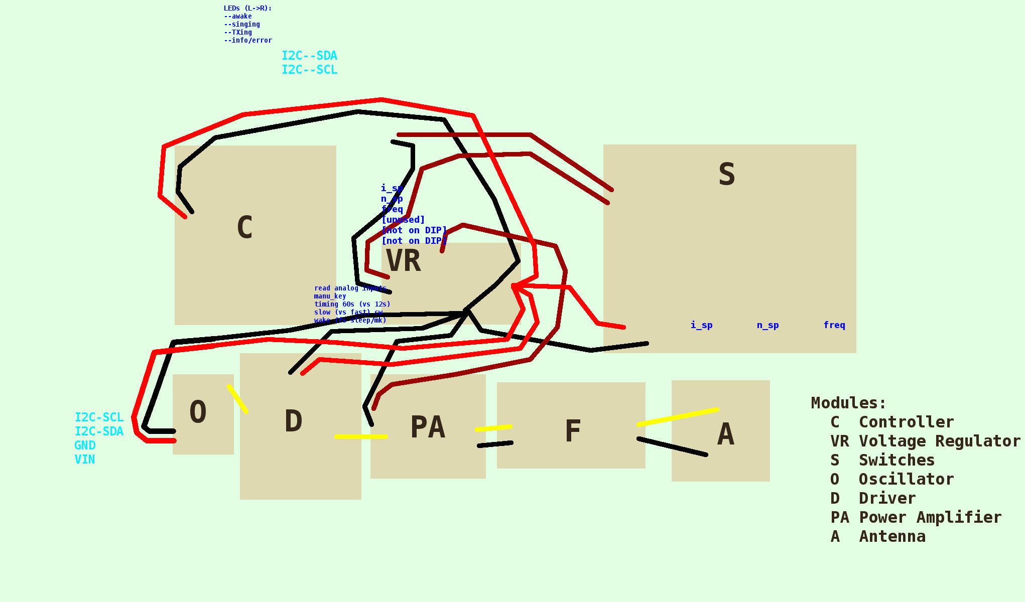
Fig. 2. Block diagram showing the modules, voltage supply lines, and RF lines. The positions of the blocks match those of the modules in the Fig. 1 picture. Modules are as follows: S switches, VR voltage regulator, C controller, O oscillator, D driver, PA power amplifier, F filter, A antenna connector.
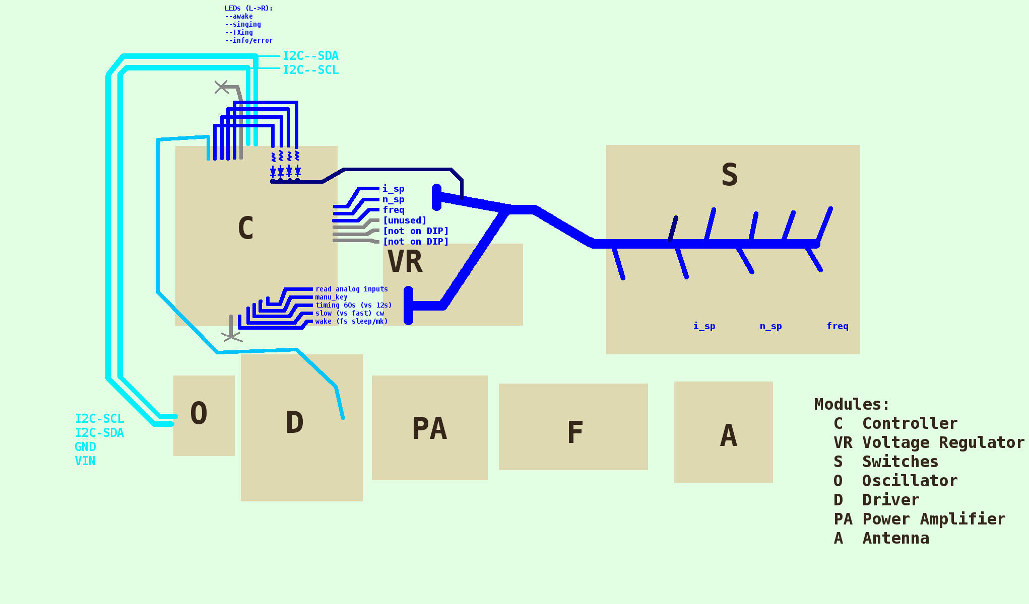
Fig. 3. Block diagram showing the modules and communication lines to and from the controller module.