19 — ARDF build and experiment progress.
2015-05-10. By Patrick.
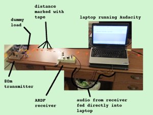
Fig. 1. Setup of transmitter, receiver, and laptop.
In my last blog entry, I wrote about getting a second transmitter ready. But we don't really have the first one ready yet. It has a controller, and a case. But that's about it. So we decided that we should finish that one first.
The first step was giving it its own power by attaching a 9V battery clip. That worked fairly well. The next and final part was the antenna.
We have a place where we go mountain biking behind the middle school. That will probably be the location for the first real transmitter trial. It's a few kilometers in length. We would like the transmitters to be heard at least that far using a good receiver. The transmitters are quite weak. I don't remember exactly but they are definitely under one Watt.
So we're starting some antenna experiments. There isn't much time left in the school year and the maker space is quite busy with the Raspberry Pis. Maybe we'll get some exprimenting done there; maybe not. Anyway, we started at home. The antenna will have to be short to be carried around in the woods. But it will have to be efficient enough to cover the forest we'll be using. I'm not sure that adding an inductor to the antenna will make much difference but we're going to make some measurements. First we used an online calculator to get some inductance values required to make a short antenna resonant on the 80m band. Those plots were interesting. It looks like we'll need from 50 to 300 uH to experiment. Then we did some simple calculations for coil sizes to get inductances in that range. We did this ignoring end effects to just get a rough idea. And we compared those calculations to values obtained using more sophisticated online calculators. We found a large plastic container and built a huge inductor. Dimensions: Length 16 cm, diameter 15.1 cm, pitch 3 turn/cm. We put taps all along it's length. It wasn't built for efficiency or strength or to have the precise inductance value we calculated. It was built for experimentation. Then we did some rough measurements to characterize it. The resistance increased linearly with tap location. The resistance from 0 cm to 0 cm (both clips connected to the same spot) was 0.6 ohm. Wow. I had some poor connections. The resistance from 0 cm to 16 cm (the entire solenoid) was 2.0 ohm. The inductance increased exponentially with tap position up to 6 cm and then linearly from then on. The maximum inductance was 260 uH.
We were now ready to experiment. But first we needed some way to measure the effect of changes in antenna length and inductance. So we tested out the following system. A 50 ohm dummy load was connected to the transmitter output. The transmitter and a receiver were placed on the desk about 100 cm apart and the audio output from the receiver was fed directly into the audio input of a laptop. The idea was to change the distance from the receiver to the transmitter and see if we could use the audio output of the receiver to make measurements that we could plot. We used audacity to record the audio. Then we could select a section of audio in audacity and go to "Analyze > Plot Spectrum". There we could move the cursor over the fundamental peak and get values for audio frequency and power. Looking at the spectrum, we could easily see that we had a sine wave when there was only a single peak and some clipping when there were harmonics.
It really worked well. As expected, the audio power increased as we closed the distance. And the frequency also decreased. I'm not sure why.
Anyway, this was a neat system to quantify the effects of changes in distance. Next, we'll be measuring the effects of changes in inductance at the base using the solenoid, changes in antenna length, and finally changes in distance that are more appropriate to ARDF.
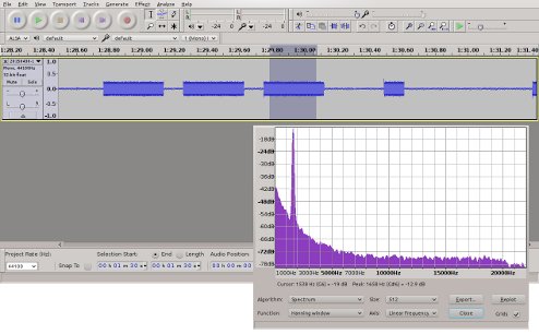
Fig. 2. Audio in Audacity with spectrum analysis window.

Fig. 3. Audio power relative to distance. Points at short distances have had clipped sine waves.
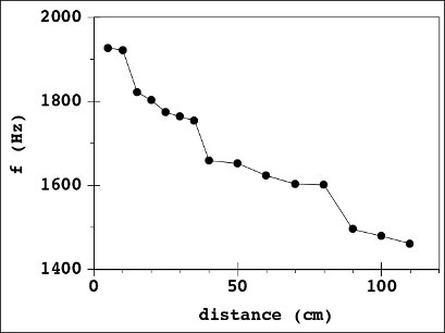
Fig4. Audio frequency relative to distance.